Kraków 2013-06-24
Radiolocation at the airport.
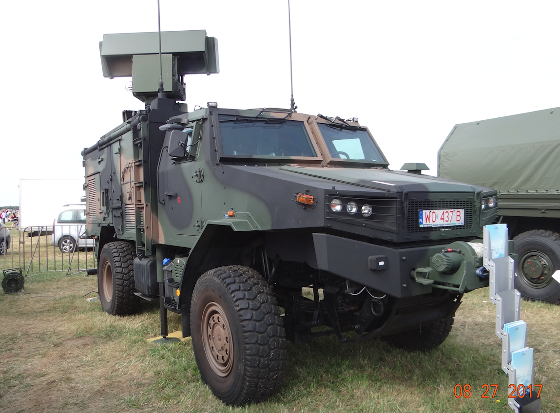
ZDPSR Bystra - A Polish-made Radar Station, PIT-RADWAR S.A., capable of transfer, installed on an armored Żubr-P vehicle. The radar is a modern, three-coordinate station equipped with an antenna with active electronic scanning (AESA). Used in short range (SHORAD) and very short range (VSHORAD) air defense systems. The radar is multi-functional and multi-purpose with versatile capabilities and applications, for example, supporting the landing of airplanes and helicopters at field airports.
Radiolocation at the airport during landing.
In the chapter "Outline of the history of air navigation. Radars 1950-1990 " we presented the radar equipment used in the Polish Army and civil aviation, and we also pointed to the successes of the Polish Radiolocation of that period. Currently, we will present the use of radiolocation in a critical moment in the flight of an airplane and a helicopter, i.e. during landing. We remind you that in other Chapters we drew attention to the necessity to enable the landing of planes in more difficult weather conditions. It was related to economy and military applications. In 40 years in the USA, the local post office noticed significant financial losses due to non-delivery of parcels on time, which meant that about 25% of flights with the mail ended at airports other than the destination. Simply put, the weather conditions did not allow pilots to land in bad weather conditions (low cloud base, fog, heavy rain or snowfall). If only the flight crew knew their exact position, if they could see the runway - landing in such weather conditions could take place.
One more note. In the 1950s / 1960s, airplanes were created, which were advertised by manufacturers as - "An airplane that works in all weather conditions." However, as has been painfully convinced, there are weather conditions that can prevent a plane from flying. That parameter is the wind force, and here we have all the typhoons, cyclones, tornadoes, hurricanes, and storms.
The first landing systems in bad weather conditions.
The first bad weather landing systems almost immediately began to develop in two ways. Some are stationary systems and the other are mobile or transportable systems. Because we must remember that it was the period of the Second World War and the possibility of transporting them was important in the use of devices.
In 1944, the first Ground-controlled approach was created, receiving the military designation AN / MPN-1 (M-mobile, P-radar, N-navigation). The set includes two PE-127 systems, each with a capacity of 7.5 kW. One works horizontally and the other works in azimuth. The system works in the high frequency (HF) and ultra high frequency (VHF) range. The set has a range of 30 miles (48 km) and a range of 4,000 ft (1,200 m). The operator sees the plane approaching landing on two screens and, through the radio communication system - the SCR-274 transmitter and the BC-342 receiver, constantly reports their location to the crew of the aircraft.
A series of mobile landing approach control radars have been developed; AN / MPN-2, AN / MPN-3, AN / MPN-5, AN / MPN-8, AN / MPN-11, AN / MPN-14, AN / MPN-25. In the AN / MPN-11 version, a significant change was the presentation of both images on one CRT screen. The AN / MPN-14 version uses a secondary radar identification device. The last version of AN / MPN-26 was in development at the beginning of the 21st century, but in 2008, the program was canceled. American systems developed as needed. The most complex ones were installed on 9 wan size cars. In some cases, some devices from a given system were installed permanently and transported only as a last resort. This situation resulted from the economic calculation. The first such solutions appeared in the mid-50s. These systems were popularly called Blind Navigation Systems. Therefore, in the CCCP, and then in the Warsaw Pact, the name Blind Landing System was adopted.
At the beginning of the 1950s, another system of instrumental approach to landing began to be developed. At the outset, we will inform you that this system is derived from the Eureka-Rebeka system from 1943, developed for landing purposes in the UK. It later found other uses, including landing. At the end of the runway (looking from the direction of the landing plane) a transmitter, actually two transmitters, was set up. One emitted waves horizontally, the other vertically. Some in the Morse alphabet were dots and the other were dashes. A unit called Rebecca was installed on the plane. The pilot steered the plane so that the signal of dots and dashes was strongest, because it depended on the plane's position. It is an early version of the locator from the more popular instrument landing system, i.e. the ILS.
As it is easy to notice, sophisticated landing systems existed already at the turn of the 1940s and 1950s. But now they speak up; security, economy and imperial interests. Depending on which of these factors takes precedence, this is how the technique and its application evolve. Therefore, in the 1950s, simpler systems were used to facilitate the landing of planes.
NDB Landing System.
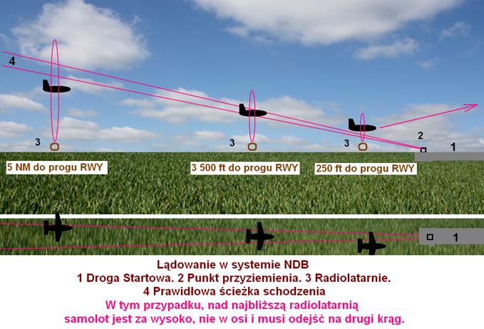
In the chapter "Navigation. Navigation History Outline ”, we mentioned the NDB (Non-Directional Beacon) navigation system, which is made up of non-directional ground beacons and receivers on board an aircraft. The landing system was developed in the USA based on the assumptions of this system. It is based on three beacons placed along the runway axis (DS or in English RWY) on the approach path at appropriate distances. During the approach, when flying over the farthest beacon, the flight crew knows the distance from the runway threshold and is able to set the appropriate landing angle. The flight over the central beacon is to confirm the correct descent path, and the flight over the nearest beacon allows for minor corrections or the plane is to go around. The nearest beacon is at the place of the decision (we either land or leave). Two ADF radio compasses are used to receive signals on board the aircraft. This system was used in the USA from the early 50's to the mid 60's and was used in commercial aviation and was replaced by the ILS system.
The NDB system in navigation is still used today due to its simplicity. Currently it consists of a terrestrial low frequency radio transmitter mainly used as an instrumental approach to airports and offshore oil rigs. The NDB transmits an omni-directional signal that is received by the ADF (standard instrument on board airplanes and helicopters). The pilot uses it to determine the direction of the NDB in relation to the airplane. To navigate using the ADF, the pilot selects an NDB frequency and the ADF compass (or arrow) points to the station's position. The NDB signal is sent with a Morse Code code which enables the identification of the NDB. NDB is used in aviation and standardized by ICAO, the International Civil Aviation Organization. Annex 10 specifies that NDB is to operate at frequencies between 190 kHz - 1,800 kHz. In North America, the frequency range is typically 190kHz - 625kHz, for offshore operations in the North Sea 500kHz - 1,250kHz, and in Brazil 1,500kHz is used. Typically NDBs have a power of 25 W to 125 W, with a receive range of around 100 NM. Higher power systems from 500 W to 1,000 W are used for further ranges. The range depends on many factors including power output, antenna, ground conductivity, frequency, site conditions, latitude, and the condition of the ADF receiver. NDB systems are highly reliable. They typically provide decades of uninterrupted service. They are cheap to buy and operate. For this reason, NDBs are still used around the world. Currently, their main application is the instrumental approach of helicopters to offshore oil rigs (since 1960). However, it is also used for an instrument approach to an airport beacon, called a LOM (Locator Outer Marker) for guidance on the ILS landing system. The LOM designates the initial ILS approach area. It is used at those airports that do not have ATC (Air Traffic Control) radars. However, the NDB has some drawbacks that make it inaccurate in functioning, especially during storms and at night. Therefore, it has been replaced by the more precise VOR and TACAN systems (for the military).
Landing technique using USL.
USL (Blind Landing Devices).
A variation on the NDB landing system developed in the West was the NDB landing system developed in the East in the Moscow Empire. The number of non-directional beacons is limited to two, and the approach to landing is carried out in the so-called "eight", with the original flight over the airport, targeting its radio station, so that the crew could establish the distance after the fourth turn to the airport. Or, as has become the norm, with the original flight over the distal beacon.
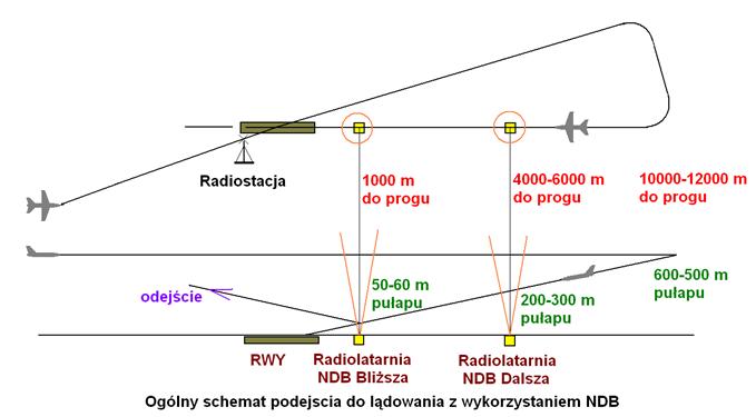
Approach to landing in the NDB system with the use of an airport radio and a radio finder. The work by Karol Placha Hetman.
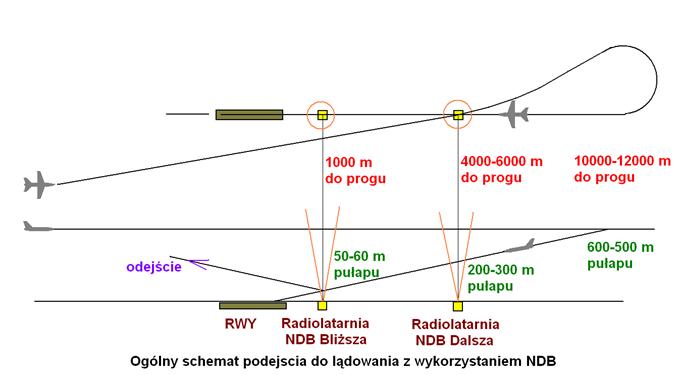
NDB landing approach with the use of distant beacons. The work by Karol Placha Hetman
In both the first and the second case, navigation was not very precise, so the system had to be modified by adding a radar, at least a two-coordinate (2D, rangefinder).
The landing technique with the use of USL (Blind Landing Devices) consists in going over a further beacon leading above the clouds, and then performing a flight with a course opposite to the runway course, with a slight deviation to the side. After the set time, a turn (No. 3, 4) is made to the landing course, aligning with its axis. During this time, the plane is maneuvered so that the radiocompass pointer points to "0 degrees" and the magnetic course coincides with the magnetic runway course. For ease of use, the pointer of the radiocompass is mounted on the same instrument as the gyromagnetic compass, on which the pointer is also aligned with the belt course. Matching both hands to "0 degrees" means a flight towards the further guide beacon with the runway course, that is, a flight along its axis. Departure from a distant beacon with a course opposite the runway allows you to create the appropriate distance needed to descend the plane with such a calculation (the falling speed on the variometer is selected accordingly, at the set flight speed), to have a ceiling of 600 m at a distance of 12,000 m. on the approach path sloping about 3 degrees from the ground, which will allow you to reach a further guide beacon (usually 4,000 m from the runway) at an altitude of about 200 m. see the ground, but the lane may not yet be visible. Visibility under clouds can be in the order of 2,000 - 3,000 m. Visibility is a relative value. Objects on the ground slowly emerge from the fog (rain, haze), initially dimly and then getting better. Contrasting objects can be seen further, and strong lights - the farthest, sometimes two or three times farther than the "official" visibility. Therefore, in severe weather conditions, runway and approach path lights are also turned on. Such a USL system was used practically during the Second World War. In 50 years, the system was supplemented with radar stations (in the east, the RSP system). USL systems have remained at airports until now (2010). They are a significant addition to the popular ILS, allowing you to control whether the ILS is working properly.
RSL complements the USL system at airports. The RSL is nothing more than a precision approach radar. Its main element is the radar observing the landing approach path in the range of several to several dozen degrees to the left and right of the runway axis, from the ground surface to an angle of several to several dozen degrees upwards. Airplanes approach to landing as per USL, but in addition, the operator of this radar makes corrections to the crew, telling the pilot over the radio whether he should make a left or right roll, decrease or increase the descent. In the East, a second radar is also part of such a system, which observes the movement around the airport completely, allowing the plane to lead straight to turn 4, to the landing course at an appropriate distance from the runway, and it is not necessary to fly over a further beacon, making the figure eight, typical for USL, making the distance runway time and speed from further beacons in flight from runway.
In the West, Approach Control, which has its own radar, is responsible for escorting to the turning point for the landing course. Only after the turn, the crew is handed over to the precision radar operator. In the East, such a system has the name RSP (Radiołokracjanaja Sistiema Posadki), translated into Polish as RSL (Radiolocation Landing System). One RSL navigator (operator) performs a function typical of Western Approach Control, and the other one, typical of a precision radar controller, called in the west PAR (Precision Approach Radar). RSP (RSL) or PAR is obviously a system older than ILS. In plainclothes, it has been withdrawn almost everywhere. But the military continues to use it for various reasons and will use it in the future. Firstly, it duplicates the functions of the ILS and may be helpful in the event of damage or disruption of the ILS, or in the event of damage to an aircraft where the use of on-board avionics is impossible. Secondly, the deployment of ILS at a foreign airport is long and labor-intensive, and the deployment of RSL or PAR takes a short time and the system is quickly ready for operation. That is why such a system is still used both in the East and in NATO and it is not treated as "outdated", "archaic" or "museum-like". Of course, the primary one is ILS (or MLS - microwave version of ILS), and in the East - PRMG, but RSL / PAR is not thrown away. Using the RSL is slightly different than using the Western PAR. The difference is a different procedure used in the east and a different procedure used in NATO and in the west in general. But it's just a question of how the system is used, since a Western precision approach radar controller could hypothetically sit in front of the RSL indicator and then work its own way, and vice-versa. In the east, the pilot reports the passage of the set points (1,000 m, 600 m, farther, closer, etc.), and the RSL navigator confirms it by giving the distance to the runway threshold. In principle, the RSL navigator turns on only in fixed places, but also whenever the pilot deviates from the runway axis or in the vertical plane - from the approach path. Then he gives him commands, for example "5 degrees to the left" or "reduce the descent by half". Each time the pilot confirms the receipt of such a command by stating his altitude. In turn, according to the NATO procedure, the so-called "Talk down". Precision approach radar controller (equivalent to the RSL navigator) gives a continuous monologue giving corrections or confirming the aircraft's movement along the established approach path. By the way, the precision approach radar controller will not say "five degrees to the right" but "heading 265" if the runway is 260 degrees. Nevertheless, with this constant chatter, the pilot is unable to engage, so commands are not confirmed here. The precision approach radar controller knows the pilot can hear him because he can see if the pilot is following his commands.
Another issue is the execution of RSL navigator (PAR controller) commands. If it instructs you to move to level flight and then go to climb, you must not ignore it, because descending to the path, especially at a short distance from the runway, i.e. at low altitude, is very dangerous.
According to the military USL procedures, the RSL allows for day landings on subsonic planes, including transport ones, at a cloud base of 150 m and visibility of 1,500 m. Of course, for different generations of radar stations these values may be slightly different.
One more note. Combat aircraft of the 50's / 60's had very high approach speeds. In order to shorten the rollout, the approach was made at a much larger angle (than today), so that some of the energy was lost on the landing gear shock absorbers.
RSP blind landing system.
RSP (Radiołokracjanaja Sistiema Posadki - Radiolocation Landing System).
At the end of the 1950s, the CCCP developed a radar system supporting the landing of the aircraft. It is modeled on American solutions. This system has been used in military aviation to date (also in the Republic of Poland), and subsequent generations are being developed in the Moscow Empire. The most popular were the systems labeled RSP-4, 5, 6, 7, 8 and 10.
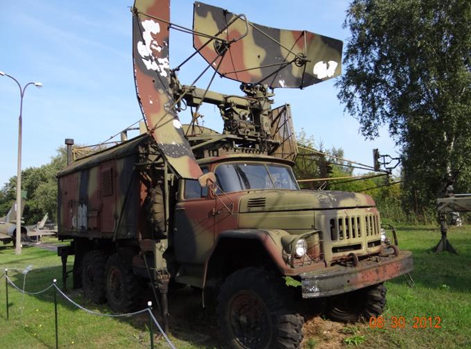
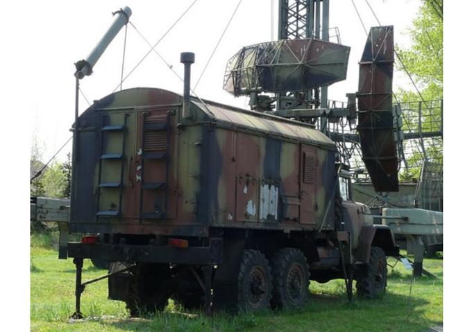
The RSP-7 system is designed to control the movement of aircraft in the airport area and ensure the landing of aircraft in difficult weather conditions, day and night. It consists of; UHF area control radar (ДРЛ). Precision radar (ПРЛ). Self-foreign control system. Two sets of radio communication РСИУ-4М or R-801. Two power generators АБ-8М. Repair devices and equipment. The system was produced in the transportable version as (РСП-7У - RSP-7U) or in the mobile version (РСП-7 - RSP-7M machine). The mobile version is mounted on ZiŁ-157 vehicles and 2PN-2 trailers.
The RSP-7T system was additionally equipped with two tape recorders for recording conversations between the controllers and the aircraft crew. There are other smaller differences as well. The system entered service in the mid-60s. Compared to the previous ones, the RSP-7 system has improved social and living conditions for operators. Electric heating and a wood-and-coal stove (the so-called goat) were installed in the operator's station. A fan is also installed. There is a potable water tank and a cooker.
Basic data of the RSP-7; Airport control radar range up to 180 km. 60 km precision radar range. Your-foreign identification 140 km. The range of the R-801 radio station is up to 180 km.
Written by Karol Placha Hetman