2022-01-04
Marek Kaiper
Radio receivers in the military aviation of the Polish People's Republic.
Military aviation in the times of the Polish People's Republic, similarly to the land forces and the navy, used a large number of radio receivers of various types over the years. From highly specialized to ordinary civilian. The latter in soldier clubs, electro-acoustic broadcasting stations on NYSA 522 cars, companies, guardhouses, remote facilities (distant and closer beacons, radio finder, radar posts), rooms for AVIA and MRŁ crews, as well as in residential trailers of the type "Miranda" for the crews of radar landing systems (RSL).
According to unverified information, in the 1950s, RPU-1 receivers with long, medium and short wavelength ranges were used, they were powered from the 127 / 220V network, in field conditions from two BAS-60 or one BAS-80 anode batteries and 2NKN-24 battery. Power supply only from the 2NKN-24 battery via a vibration converter. There is a compartment for accumulators and batteries in the receiver housing. They were then replaced with portable, battery-powered transistor radios of the Dior "Ewa", "Alina" type or similar, placed in a leather case with a shoulder strap. In aviation, apart from communication receivers, specialized aircraft radio receivers were also used. They were designed to receive radio navigation signals RSBN, RSDN (A-720, A-723, A-737), PRMG, radio beacons (radio compass receivers), signal transmitters MRM-48, NR-2307, MRM-W (aircraft receivers MRP- 48, MRP-56, MRP-66). The radio compasses could also be used as an emergency receiver of commands from the flight control station in the event of a failure of the radio station (channel 21).
It is impossible to identify the radio receivers used in the Polish Army without a detailed search in military archives. Many types of radio receivers as well as tape recorders or teletype recorders were part of mobile devices, so they were not included in the equipment lists. Hence the difficulties in determining the number of types of receivers used in Polish aviation. Also during the modernization of the radio station, older types of receivers were replaced with newer ones. The use of the Russian radio manual is also not reliable, due to the frequent use of other older equipment in export versions by the Russians. In the various Polish equipment lists, generalizations were often used, eg R-250, R-870 or EKD with references to "all types". Confusion was also caused by the desire to conceal the purpose of non-public equipment, radio stations, receivers and adapters to them were called devices, e.g. devices R-348, R-355, R-375A, R-375P, R-383, R-396R or the laconic name HF disturbances "with reference to" all types "or the R-333 pickup for the R-335 phototelegraph or the VHF or KF panoramic pickup with reference to all types. Therefore, there may be inaccuracies in the study and the list of receivers is probably not complete. In the period from 1944 to 1950, the problem was to determine the types of receivers made in Germany, America and Russia used in Polish aviation.
In the USSR, a military equipment record system was introduced, in which the groups of equipment were identified by the next letter of the alphabet and the subsequent registration number. Radio transmitting and receiving devices, radio emission analyzers as well as reconnaissance and countermeasures devices were designated with the letter R. The numbering defined the intended use of the equipment. The numbers from 0 to 99 (0XX series) were coded radio communication equipment, from 100 to 199 (R-1XX series) general military communication equipment, from 200 to 299 (2XX series) communication devices, from 300 to 399 (R-3XX series) electronic warfare equipment, from 400 to 499 (R-4XX series) radio lines, from 500 to 599 (5XX series) secret communication devices, from 600 to 699 (R-6XX series) naval communication equipment, from 700 to 799 (7XX series ) electronic reconnaissance, jamming and satellite communications equipment of the navy (R-720, R-721 receivers, R-713 panoramic receiver), from 800 to 899 (R-8XX series) air force and air defense equipment, from 900 to 999 ( R-9XX series) electronic reconnaissance and jamming devices, radio nodes of air forces. Before introducing the markings, radio receivers and radio stations were marked with various symbols, e.g. US-P, US-9 receivers (a copy of the American BC-348 receiver), RPU-1, AS-2, RAF-KW, RSIU-3, A7-A radios etc. Some types of receivers had old names, the same receivers from newer production had new markings. For example, the AS-2 radio receiver was called R-250 and the marine version produced was called R-670 "Rusałka", the KF - VHF R-160P receiver was also called R-260, R-680 and R-682 "Kaszalot" ( in sea version with the frequency range 3 - 99.99 kHz), R-876 "Prizma" for military aviation and under the name "Sosna" for civil aviation.
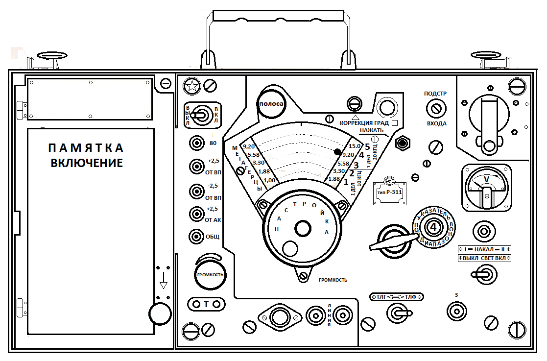
In the Polish Army, there was no rigid division that, for example, the 3XX series receivers were used only in reconnaissance units and the 1XX series in the land forces. Receivers were allocated as needed. For example, R-326 receivers were installed in ADK-11 shelters (quartermaster command shelter), and R-311 (1-15 MHz) receivers were stored in inviolable (military) stocks in sub-divisions of flight command squadrons (ddl), renamed in 1978 into communications battalions and flight insurance. They lasted there until the second half of the 90's. These receivers were also included in the set of various radio stations. They were powered from the 127 / 220V mains through the WS-3 rectifier, in field conditions from the 2NKN-24 battery through the WP-3M2 vibration converter or from the 2NKN-24 battery and the BAS-G-80 anode battery. The rechargeable battery and batteries were housed in the receiver housing. They were equipped with a coiled rod antenna (Kulikowa type) 1.5 m high, a rod antenna 4 m long, and a "oblique beam" wire antenna, 12 m long. An interesting feature was the use of eight identical 2Ż27L electron tubes in the receiver's construction. Some types of receivers enjoyed longevity in aviation, for example the Russian US-P receiver (173 kHz - 12 MHz) was developed in 1948. It was a further development of the series of US receivers (Universal Supergeterodin) produced since 1937. It was equipped with PAR 8ss beacons until the end of the People's Republic of Poland.
Communication receivers in the meteorological service.
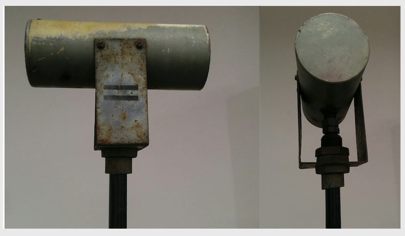
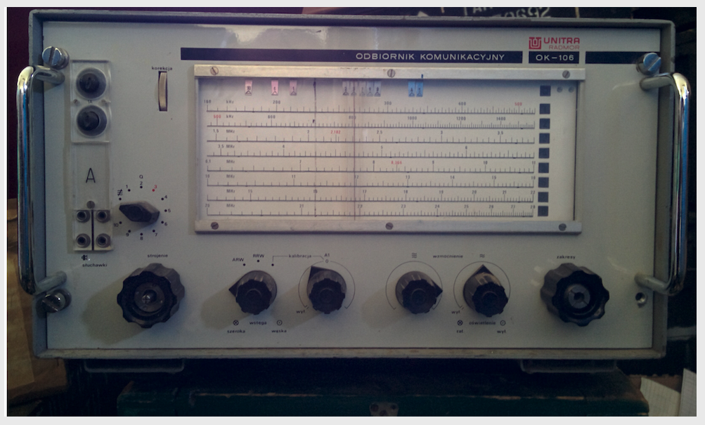
In this service, communication receivers of Polish production were mainly used. The long-wave receiver from Radiotechnika Wrocław ODF-100R with a ferrite antenna in the shape of a horizontally arranged cylinder placed on the mast was used there for many years. It was designed to receive frequency-modulated radio signals and control the demodulated teletype signal (F1 telegraphy) or telecopy devices (F4) to receive synoptic maps. The receiver could receive one of the three stations in the 90 - 140 kHz band. It had three switch selectable channels, factory tuned to 129.5kHz (the national weather station) and 106.7kHz (the German Weather Bureau's DCF-26 station). Channel 3 factory tuned to the frequency of 134.2 kHz was a reserve, it could be tuned to any frequency after tuning the RF circuits. and replacement of quartz resonators. Many of these receivers survived in the PSM-2 field weather stations until the end of their operation after 1991. Another receiver used at meteorological stations was the OMNK-111 produced by the Maritime Radio Ship Service (MORS) operating in the 14 kHz-32 MHz range, divided into 11 sub-ranges switched on by a key switch. It enabled the reception of signals with A1, A2 and A3 emission. Other Polish receivers were MORS OK-102 (further development of the OK-2 communication receiver), OMNK 112 and Radmor OK-106.
The Radmor OK-106 communication receiver was a transistor superheterodyne receiver operating in the 160 kHz - 28 MHz range. It could work as a tunable or channel receiver with 10 freely selected frequencies in the range up to 10 MHz. The use of additional frequency conversion enabled cooperation with a converter with the operating frequency of 465 kHz for the retransmission of radio signals emitted by international meteorological centers.
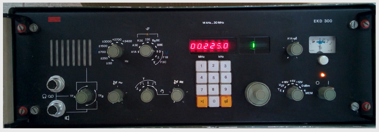
Foreign communication receivers were represented by the Czechoslovakian Tesla Lambda and the German (East Germany) RFT EKD-300 and EKD-500 receivers.
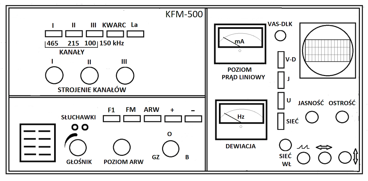
For some types of receivers, the FM / AM KFM-500 converter was used to receive telegraph signals. It was an adapter enabling the use of a communication receiver to receive frequency modulated signals and control the demodulated signal of a teletype or telecopy machine (synoptograph). The converter had 3 channels. The first channel with a frequency of 465 kHz was used to connect the OK-106 and OMNK-112 receivers, the second channel with a frequency of 215 kHz and the third channel with a frequency range of 100 - 500 kHz. The KFM-500 converter was equipped with an oscilloscope to facilitate the adjustment of the operating parameters of a given channel.
Radio receivers for aviation communication.
After World War II, communication with the crews of military aircraft in Poland and the USSR was carried out on short waves. At that time, Russian KF receivers were used, mainly as those on duty at command posts.
In aviation short-wave communication, the US-P (ground radio station RAF-KW), US-9 (radio station R-820 (RAS-KW)) receivers were used. 5) with the US-P or US-8 receiver, R-807 with the US-9 receiver, R-808 with the US-9DM receiver, R-836 radio with the US-8 receiver. At airports, the R-673 superheterodyne listening receiver (12 kHz-25 MHz range split into 10 sub-ranges) was used as the duty receiver in the command post (SD). It was built on 15 lamps (pentodes) 2Ż27L and was equipped with a frame or rod antenna. Power supply of the receiver from the 220V network. Later, the R-250, OK-106 and OR-1205 "Oleander" receivers were used. Only the loudspeaker connected to the receiver in the radio-office of the communication node by a wired line was installed on the SD.
The transition of the Warsaw Pact countries in short-wave military aviation communication to the VHF range made it necessary to purchase new R-800, R-801, R-802, R-860, R-863 radio stations and new ground radio stations (R-811 (RASK- 1A), R-814 (RAS-UKW), R-821 (RSK-1M), R-824 (RAS-UKW-M2)) as well as VHF listening receivers (R-870). The next step was the VHF / dmF (VHF / UHF) R-831 radios with R-802 and R-803 aircraft radios. Shortwave communication remained only in bombers, long-range transport aircraft and in ground communication networks between command posts. The RPS receiver (143/280 kHz - 24 MHz) was installed in the An-12 long-range transport aircraft.
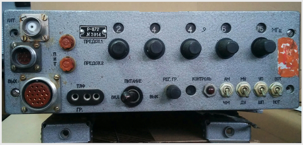
Four-channel VHF receivers with replaceable R-800 quartz from airplane radios with the same names were tuned to zero beats. The external quartz resonators were labeled by number, not frequency, and were inserted into slots on the front panel. R-800 receivers were used in R-811, R-814, R-821 radios and in ARO radio reception rooms. The VHF R-801 radio receiver was equipped with 6 channels tuned successively for zero beats and a mechanical frequency scale scaled in wave numbers (601 numbers). It was used in the VHF R-824 radio station and in the ARP-6 radio finder. The VHF R-800, R-801, R-870M and dmF (UHF) R-871 receivers were equipped with conical disc antennas.
Shortwave receivers R-311 and Amur-2 or R-154-2 were installed in R-118 and R-820M radio stations, two R-250 receivers with an R-327 adapter were installed in R-830 radio stations, the R-155 receiver and R-311 or R-326 in the R-140 radio. They were used for short-wave radio communication in the command network. R-250M2 receivers could work with symmetrical or asymmetrical antennas with a wave resistance of 60-400 ohms, an "oblique beam" antenna and a rod antenna. Apart from the radio stations, they were also part of the R-377 device (a control and command device for interfering radio stations, eg R-325). KF / VHF R-839 radios equipped with the KF R-311 receiver and the VHF R-870M receiver were also used. And also KF / VHF / DMF R-849 radio stations on the UAZ-452A car (minibus) equipped with the KF R-873 receiver, the VHF R-870M receiver and the DmF (UHF) receiver (220 - 389.9 MHz) R-871. This enabled correspondence with airplanes equipped with the VHF R-802 radio and the DmF R-803 radio or the VHF / DMF R-863 radio. The VHF / DMF (VHF / UHF) receiver Unimor OR-6701 was mounted on the SSD-2M starting command post on the STAR-266 car and was located in the "pilot's house". This receiver consisted of two receiver blocks with the numbers 6731 (VHF) and 6732 (dmF). It was equipped with a conical-cylindrical cage antenna A0222. The VHF R-852 receiver was used to cooperate with the ARK-U2 aircraft radiocompass.
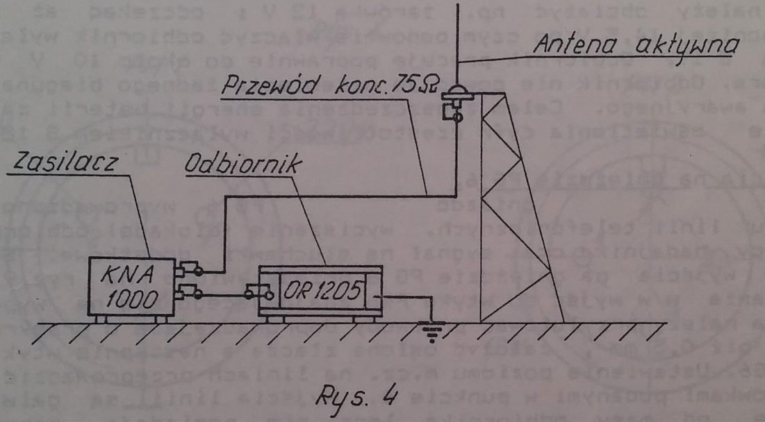
Polish receiver ŚF / KF (MF / HF) Unimor OR-1205 "Oleander" (100 kHz - 29.999 MHz) is used as a listening device in flight control towers and is part of the RL-3301 "Krokus" radio beacon set. It can work with three types of antennas: the active RFT KAA-1000 antenna with the KNA-1000 power supply (18V, 100 mA), the AP-6 rod antenna through the DN1342 connector and the 30 m long cable through the DN1342 connector. The receiver is powered by 230V or in emergency from a 12 V battery with a capacity of approx. 150 Ah.
APR-7 and APR-8 stationary beacons were equipped with an R-880M receiver with a frequency range of 150 - 1500 kHz. An interesting battery (battery with voltages of -2.7 V, +1.35 V) tube receiver from the aviation border was the R-254 intended for airborne troops. It only received VHF signals with frequency modulation. It had two work regimes, "Search" and "Receive." In the first one, it made it possible to find discharge containers with equipment or supplies equipped with an R-128 radio signal transmitter. In the second, accepting commands and messages. The receiver was equipped with a handset, the direction tracking to the radio signal transmitter was performed by rotating the receiver, which changed the volume of the handset. A modernized version with reduced dimensions of the R-254M was produced. The newer version of the search receiver was the R-255PP with the R-255MP radio-signaling transmitter, weighing 4.5 kg, attached to the landing pods.
Reconnaissance radio receivers.
Radio reconnaissance is used to detect radio emissions, targeting them, i.e. determining the direction to a working source of electromagnetic radiation and analyzing this radiation. Determining the frequency, type of modulation, width of the characteristic, polarization of radio waves as well as the duration of the pulses, their shape, frequency of repetition and other parameters. The reconnaissance receivers were designed to receive a small frequency band, which allowed for precise control of its range. These tasks were mainly intended for receivers manufactured by the USSR of the 300 series, receivers of this series were secret at that time.
Recognition radio receivers with a built-in oscilloscope indicator are called panoramic (panoramic) receivers, eg Mechanikai Laboratórium Budapest UP-3. In English panoramic receiver in Russian panoramnyj radioprijemnik. Receivers without a built-in oscilloscope can also be used to analyze radio emissions after connecting to them an adapter with an oscilloscope indicator (R-712, R-319 or other). They are called panoramic adapter or signal spectrum analyzers (Russian panoramnaja pristawka, English panoramic adapter). Reconnaissance receivers built into the radio finder with an indicator on the oscilloscope lamp and a special antenna system indicate the direction of the working radio station (Orzeł-1M on the GAZ-69 car, R-363 on the ZiŁ-157 car, R-359 on 2 ZIL-157 cars, TK- 5 on two Ural-375 cars, R-344 on three ZiŁ-157 cars, R-391 on two ZiŁ-131 cars). They were used in the Radio Engineering Brigades, Radio Recognition Centers and Radioelectronic Countermeasures Centers for OPK troops and other WRE units.
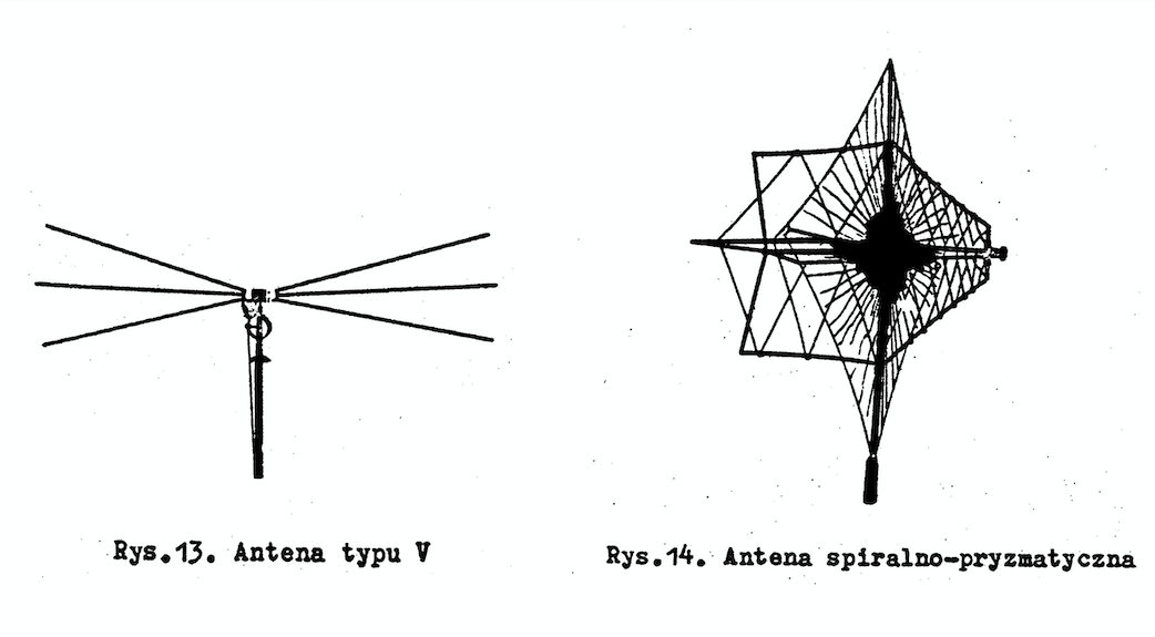
Identification VHF receiver R-375P (20 - 500 MHz) powered by alternating voltage 110V, 127V, 220V 50 Hz and 115V 400Hz or from batteries through a semiconductor converter. It was intended for auditory reception of telephone or telegraphic broadcasts with frequency or amplitude modulation. It could be used in radio finders. The receiver was equipped with 3 antennas (V type (40-120 MHz), spiral prismatic (115-210 MHz) and spiral conical (210 - 500 MHz)). The antennas were mounted on two 8 m high masts with rotating devices. The V-type antenna rotated vertically within 90 ° and could be set in three fixed horizontal positions. The remaining 2 antennas were placed on the second mast with a rotating device in the horizontal plane within 360 degrees.
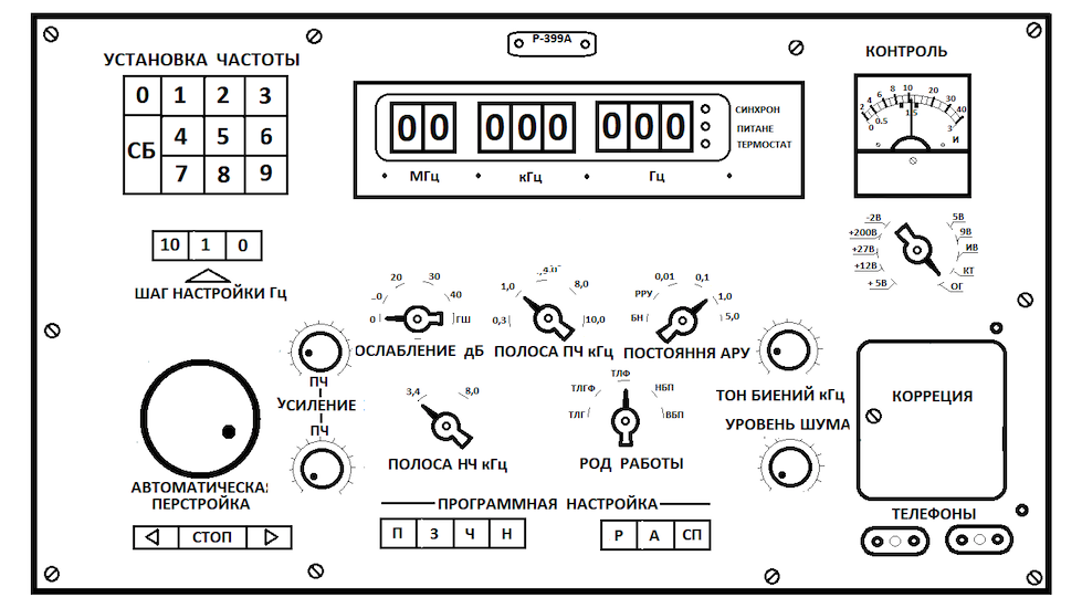
The modern R-399A shortwave superheterodyne receiver was the latest in the 3XX series. It was designed to search and receive telegraph and telephone signals without additional demodulating devices in the entire range of received frequencies (1 - 39.999 MHz). The receiver is equipped with 60 memory channels and a display on digital lamps (digitrons) IN-12. The receiver could be powered from the 230 V mains through the KB2A power supply or with direct voltage + 27 V from the KB2A power supply. The R-399T analyzing attachment was used for the R-399A receiver.
The aviation accent of the WRE devices (radio-electronic warfare) used in the Polish Army were the passive reconnaissance and tracking stations for the transmitters of aircraft devices POST-2, POST-3M "Lena" (2 - 40 GHz) on the ZiŁ-157 car in the KUNG-1M body, 2PN antenna trailer -2 and the supply shelter on the ZIŁ-157 car with the KUNG-1M body, in which the diesel-electric ESB-8H-2B units were placed. The name of the station was the first letters of the words in Russian POiskowaja STANCE type 3 modernized. It was designed to detect and analyze radar signals, mainly aircraft radars, as well as radio signals from altimeters and transponders. After modernization, the POST-3M stations are still manufactured in Russia. The next station was the reconnaissance station RPS-6 "Łucja" (1RŁ234) on the GAZ-66 car. Its task was to receive, track and analyze the signals of radio navigation devices in the range of 0.5 - 9.0 GHz. The air accent was also the R-388 station recognizing and jamming the TACAN navigation system in its three channels: azimuth, distance and data transmission. Range at high altitudes of 300 km at low 20 km. The station was located on the ZiŁ-131 car, in the K-66-U1D body made of non-flammable material. The body was divided into two rooms: a shelter room and a power supply unit with one AB-8T / 230M generator set. In the case of radioactive contamination, the aggregation room was a vestibule where deactivation procedures were performed before entering the shelter room. The station was equipped with a receiver with a range of 1025 - 1150 MHz with automatic tuning and stopping on the received channel of the TACAN system. The received signal activated the interference transmitter with an average power of 250 W on the GS-7B, GS-35TB generation lamps. This resulted in false results on the indicators of the aircraft's on-board apparatus or a condition proving its failure. Powering the station from the 230 V mains, the AB-8T / 230M generating set or the EU-131-8-T / 230 backup power device driven by the car's engine. As one of the few stations, the station was equipped with an EP-2 electric vacuum cleaner enabling the removal of the effects of radioactive fallout. It was also equipped with the R-405MPT-2 radio link, which allows to receive commands from the command post, the R-105M radio station, the DP-5B X-ray sensor, the OW-65 heating and ventilation device, the FWUA-100-N-12 filtering device, and the TDM air flow meter -2004. Also the SPN-30 Jadwiga 3 radar response station on the URAL -375 vehicle was intended, inter alia, to disrupt aircraft radars for observation of the area.
Additional devices.
Some receivers were equipped with additional devices, VHF or KF adapters (converters) enabling the reception of telegraph or telecopy signals. The R-327 or TOPOL 2M devices were designed to convert the telegraph signals received by the receiver with frequency modulation into telegraph signals with amplitude modulation, activating the teletype.
The R-376 device was used for the R-250, R-250M, R-670 and "Kalina" (1-35 MHz) receivers. It was intended to receive single-side telephone broadcasts. The R-250 / R-250M, "Kalina" and R-309 "Barley" receivers could work with the R-371 device, which was designed to capture radio telegraph emissions with FM or AM modulation and DCzT (two-channel frequency telegraph) emissions.
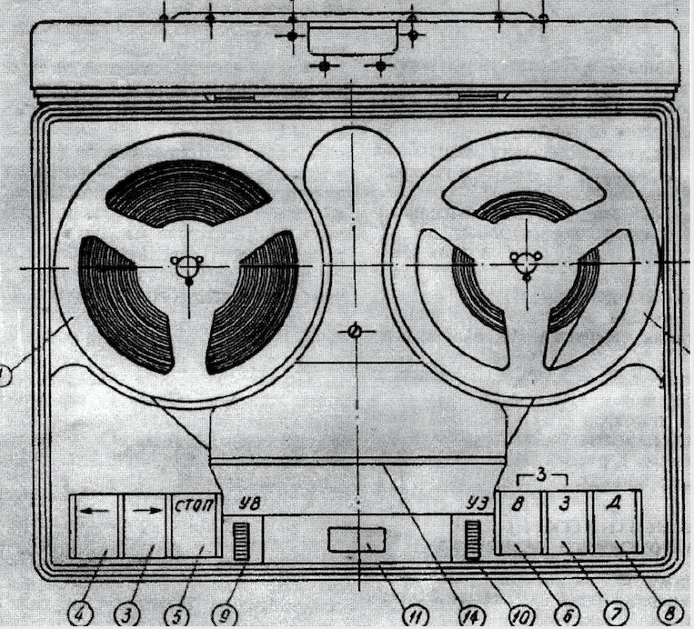
In order to automatically record impulse reports transmitted at high speed, the R-355 radio communication control and monitoring device was used. This device used the R-250M receiver and the P-181 disc tape recorder. It secured communication with portable correspondence radios transmitting at high speed to prevent tracking.
Additional devices were also spectrum analyzers for optical analysis of telegraph and telephone signals while observing them on the screen of an oscilloscope lamp. The analyzed emission could be photographed or recorded with a tape recorder. KF radio signal analyzers R-712 were used for optical observation of radio signals received by the R-250M2 receiver. R-319 panoramic indicator was used to analyze the signals received by the R-313M receiver. This version could receive telegraph signals using the R-327 telegraph set-top box and the T-51 teletype receiver. For Mechanikai Laboratórium (ML) receiver; The Budapest R-1250 used a panoramic DF attachment with the option of shooting imaging.
The VHF R-375P reconnaissance receiver cooperated with the R-375A analyzer. It made it possible to analyze the signal obtained from the receiver's wideband output and to find single-sideband audio emissions with frequency multiplication in the spectrum. The analyzer had a smoothly tuned frequency range of 4 -350 kHz, divided into 2 sub-ranges.
The R-399T spectrum analyzers were part of the KF R-330U, R-325U and R-378 interference stations. The VHF R-330U (30-100 MHz) interference station on the Ural 375 car, located in the K-375 body, was intended to interfere with the enemy's VHF communications and to provide bearings for operating sources of radio communication. It included the R-415 radio line, portable VHF R-159 radio, battery-powered radio with mains adapter, portable recorder (tape recorder) P-180, KF-VHF R-160P (1.5 - 59.999999 MHz) or R receivers -323 (20 - 100 MHz), R-381Т2-1 radio finder, R-399T analyzer. The KF R-325 interference station was equipped with an R-399A receiver, AZID-1 (R-415) radio link, AI-011 data transmission device, and KF / VHF R-381T1 reconnaissance and detection device.
End.
After the liquidation of the Warsaw Pact, purchases of radio receivers were made in Western companies. Receivers from Tales TRC-243, TRC-298 TRC-623, TRC- 8025, LCR-3400 and TC-5400 as well as Rohde & Schwarz EK-890, ESM-500, EM-510, EM-550 were purchased. Russian receivers were used until their service life was exhausted. Many Russian KF receivers, after withdrawing from the army, found a second life in scout, Lokowo or Polish Radio Amateur Radio Clubs. Radio stations, such as R-820, R-118, R-140M, were often installed in club rooms, dismounted from car bodies. Currently, military receivers are also popular with private amateurs who can purchase them at Military Property Agencies. Various types of KF receivers were used in amateur radio, e.g. US-P, KW-M, US-9, R-250. R-155, R-311 and others. These receivers were often modernized by hams, adjusting them to their own needs.
Bibliography:
Demoduliruuszczije structure of the tip "Topol - M", technically described and instructions after operation.
DE-1205, Operating documentation, radio communication receiver OR-1205, year of development 1986.
Diktofon P-180 descriptions and instructions after the operation in 1963.
Technical service manual for the R-820M radio, Warsaw 1977.
Krotkovolnovo radiopryjemnoje contraption of tipa R-1250, technical description of instructions on obturation and technical support of the ear, Budapest.
Terrestrial and on-board radio navigation and aviation communications equipment, Poznań 1972.
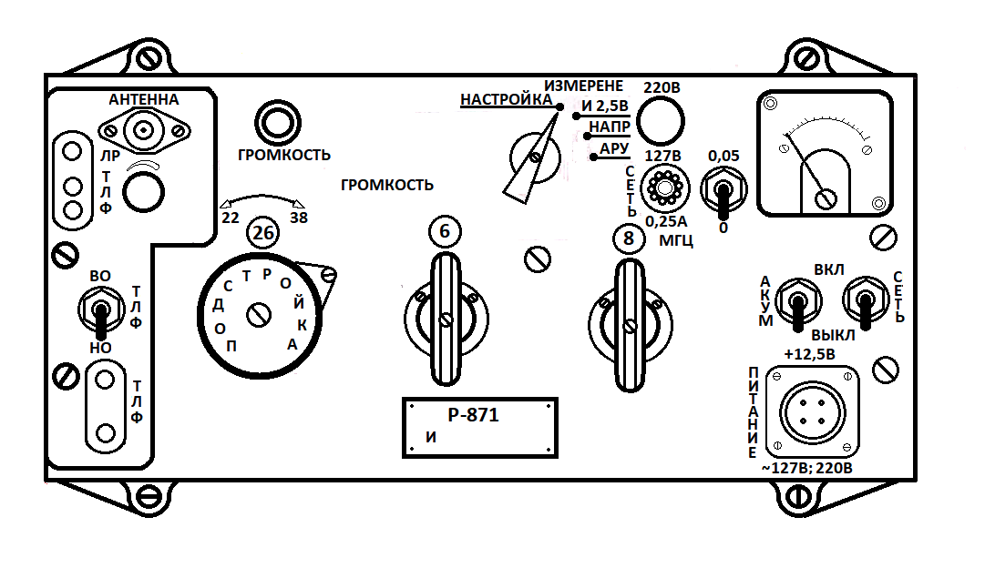
R-871 receiver, technical description and operation, Warsaw 1973.
Description of the R-311 receiver, Warsaw 1962.
Description and operation of the US-9 receiver, Warsaw 1962.
R-870M receiver, technical description and operation, Warsaw 1973.
Pali Aleksander, Radio War, Warsaw 1966.
R-250M2 radio manual, technical description and instructions after operation.
Radio station R-839, description and operation, Poznań 1976.
Radio station R-849, technical description and operation, Warsaw 1981.
Written by Marek Kaiper