Kraków 2022-11-16
American LFB navigation system.
The LFB radio navigation system was developed in the USA from 1929. This system was initially designated as LFR (Low Frequency Range). But it did not work and was modernized. This is how the LFB (Low Frequency Beacon) and LF-RNG (Low Frequency Radio Range) systems were created.
The LFB system was put into operation in the USA at the beginning of the 1940s, and in Europe it was used from around 1949. The system was constantly modernized and automated. The LFB was used until the end of the 1960s.
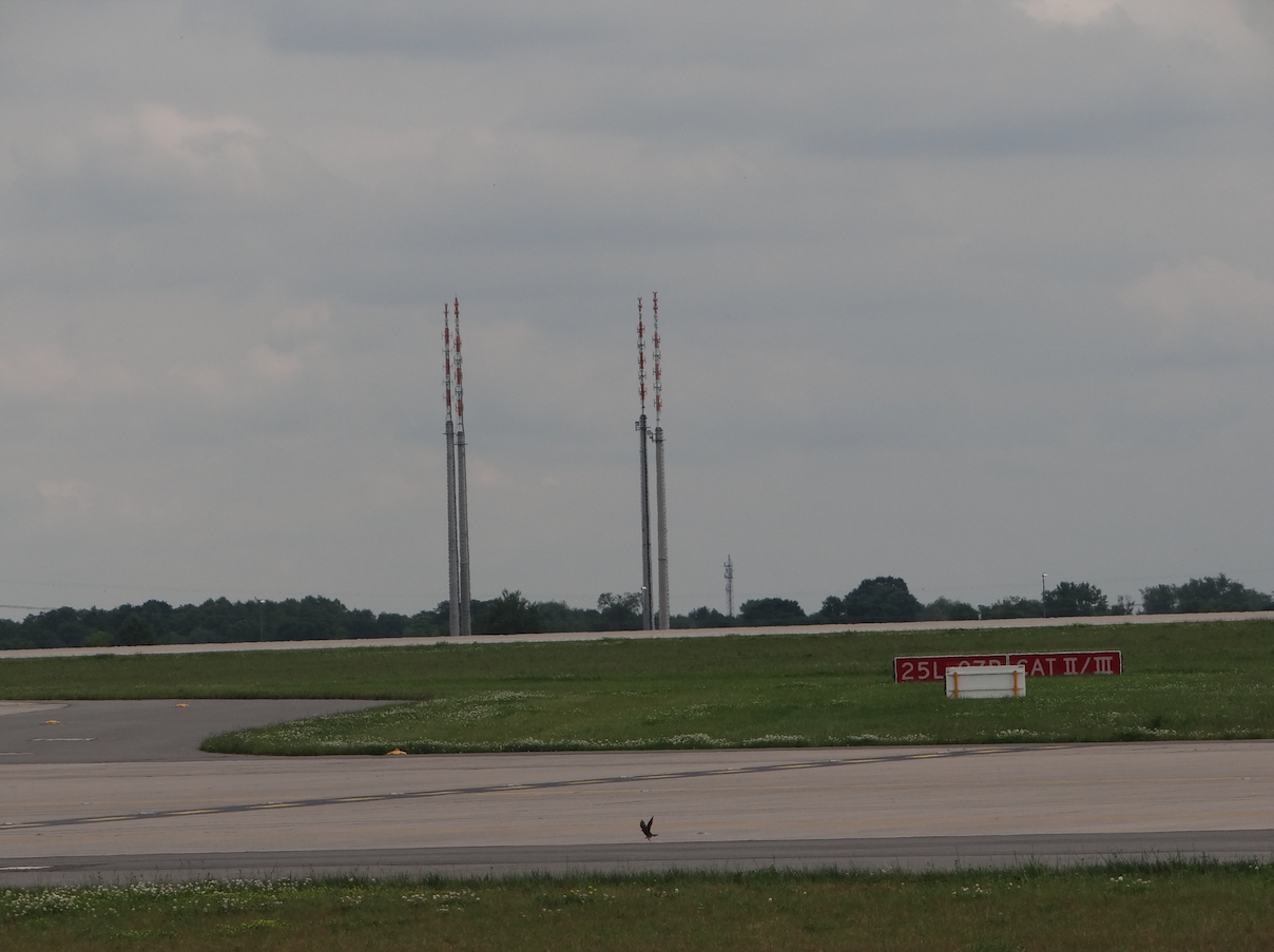
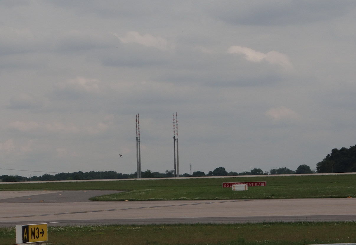
The LFB system was based on ground beacons. Each radio beacon consisted of two masts, and at the intersections of air routes - four masts. Two masts were placed side by side, about 20-30 m apart, on both sides of the marked air route. One of the masts was transmitting radio signals - dots, and the other was transmitting radio signals - dashes. The intervals were chosen so that in the ideal middle of the route the pilot heard a steady signal in his headphones. When the plane deviated from the route, dashes or dots were more audible. Thanks to this, the pilot corrected his flight.
After the modification, the flight over the beacon was signaled in the cockpit with a white light. Then the crew moved the radio direction finder to the next beacon. The audio signal was left as an emergency.
When modernizing the LFB system again, a new device was introduced in the cockpit of the flight crew; radio-compass. The radio-compass was mounted on the front center panel in a horizontal position. It was clearly visible to both pilots. The radio compass had two hands, and its dial had an angular scale and a movable compass rose. One hand showed the direction to the beacon that the plane had already passed, and the other hand pointed to the next selected beacon. If the hands overlapped, it meant that the plane was flying perfectly along the route. Halfway between the beacons, the hands of the radio-compass switched positions, turning 180 degrees. It was also an indicator of the exact position of the aircraft. It was the same with the radio beacon. In the cockpit, the control lamp of the flight over the beacon was left.
Also on the appropriate radio beacon, the plane began its descent to land. The crew knew exactly how far it was to the airport. This was confirmed by one or two beacon additions, over which the plane should be at the appropriate altitude.
Radio beacons were initially placed along air routes between airports. Over time, they began to be placed at the intersections of air routes. Then there were four masts that broadcast the appropriate sequence of signals.
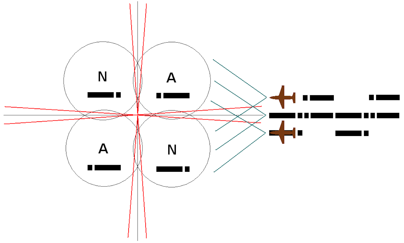
Image Description: Four antennas broadcast A1A's "A" and "N" characters, forming two or four narrow zones of overlapping characters with equal loudness. The pilot steered in such a way as to hear a continuous signal in the headphones of an ordinary medium-wave receiver.
The system and its execution was so careful that the masts are still standing (2014) and are used as beacons of the NDB system. These beacons operated in the range of 200 to 600 kHz. The range of the beacon was about 300 km.
Written by Karol Placha Hetman