Kraków 2010-11-22
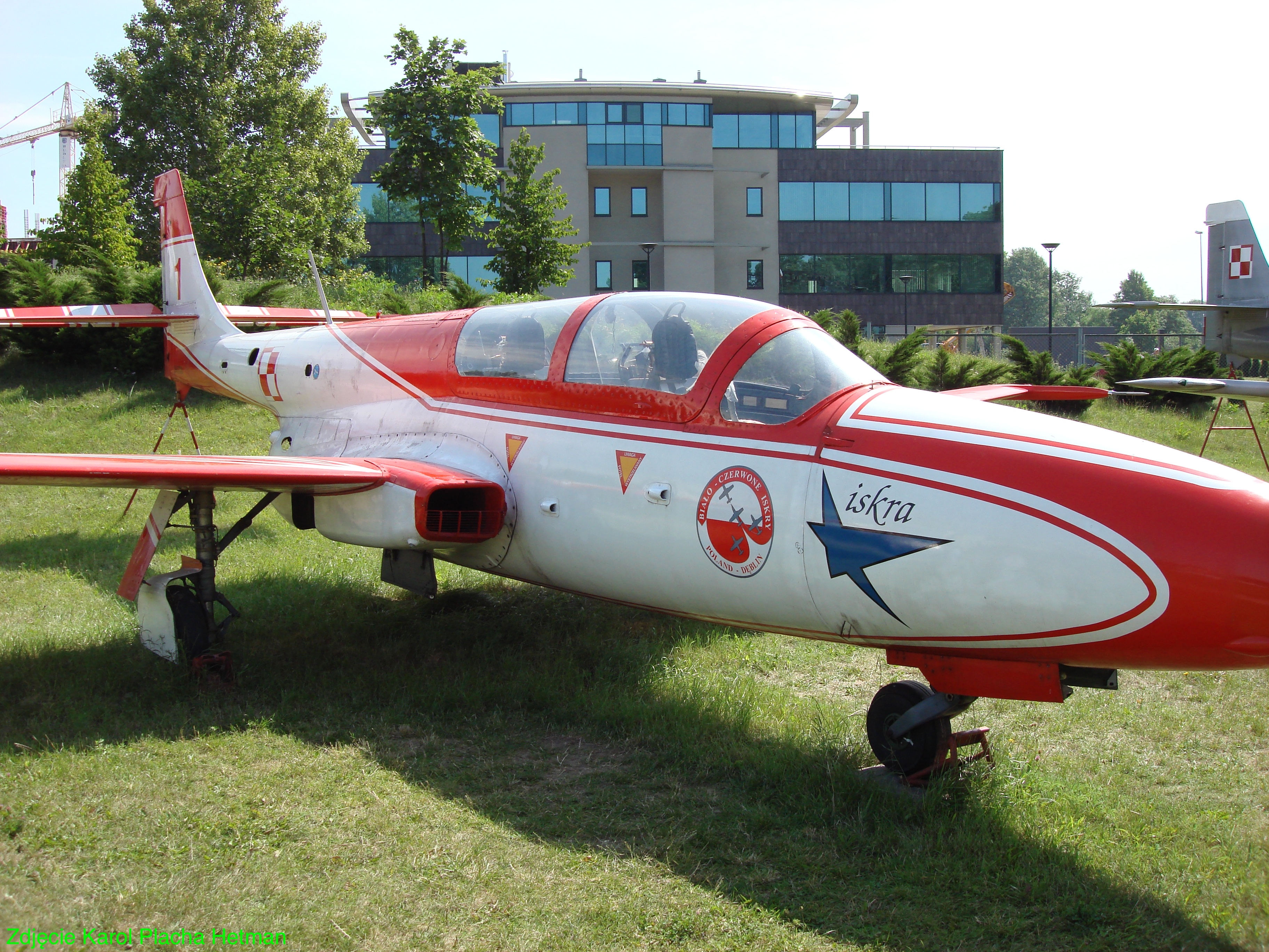
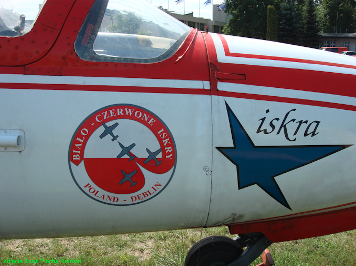
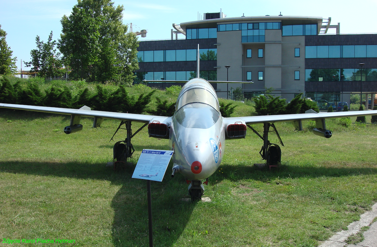
PZL WSK Mielec TS-11 Iskra.
171b Section 5 February 1960. Trainer and combat aircraft.
PZL TS-11 Iskra design.
The plane is a two-seat, single-engine, training aircraft, built in a classic layout with a straight wing. Semi-monocoque construction. The plane can be used as a light combat aircraft. Airplane intended for; training in basic piloting, training in non-visible flights, aerobatic flights, high-altitude flights, shooting, bombing, navigation, and aerial photographic reconnaissance. The aircraft is used for second-level training, after piston-powered or turboprop aircraft, and to maintain the habits of qualified military pilots.
The wings are straight with a trapezoidal outline. They have a lift angle of 2 degrees. The designers selected a relatively thin laminar profile of NACA 63209 at the root and NACA 63009 at the end, amounting to 9%, with geometric buckling ensuring stability at operating speeds.
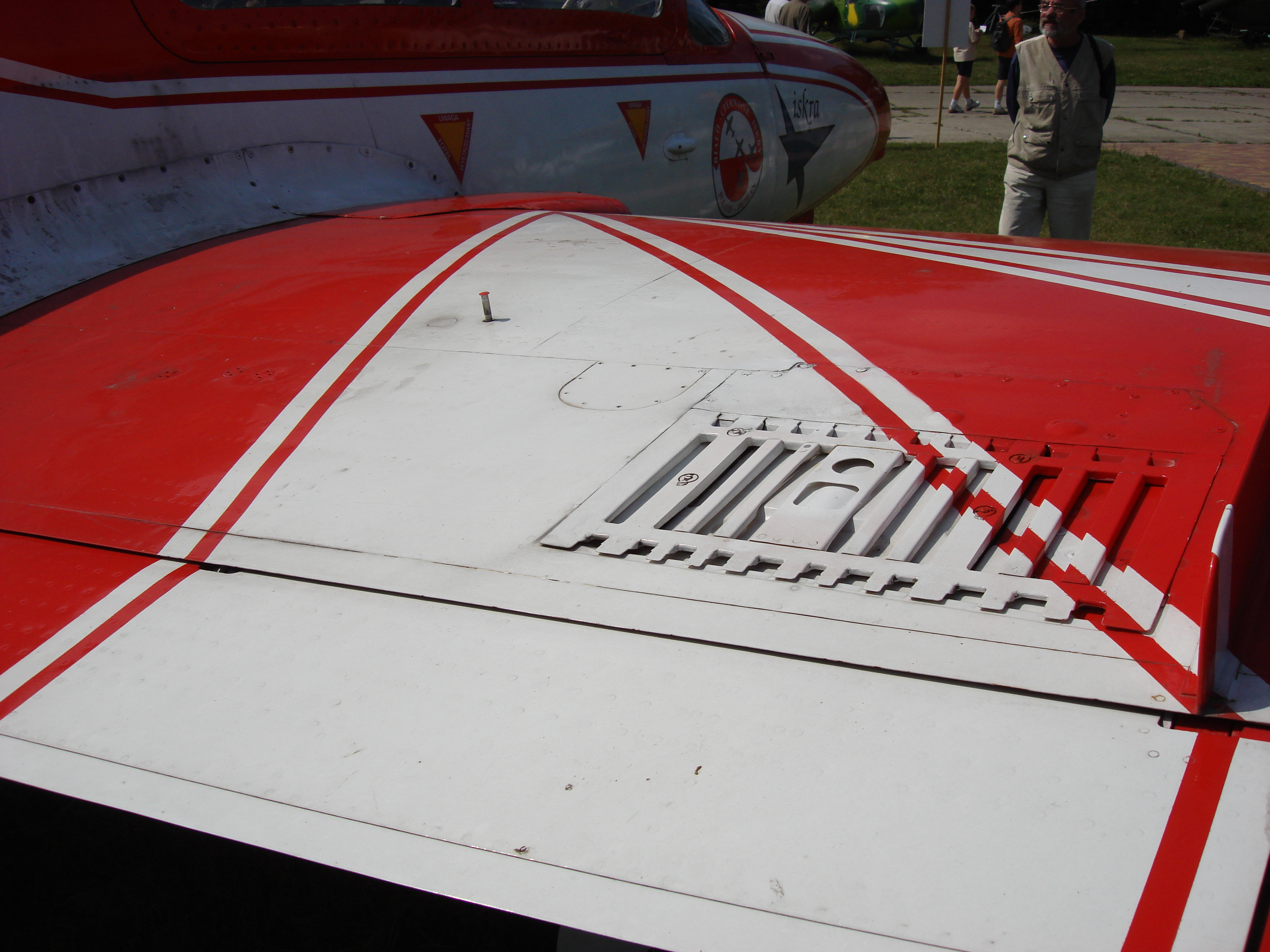
The airfoil has a half-shell, all-metal structure with a trapezoidal outline. The attachment to the hull is provided by two main spars: front and rear, with a caisson between them. The caisson is the basis of the wing's strength system. The skeleton of the airfoil consists of 15 ribs and numerous stringers on which the metal covering of the outer surface rests. The caisson houses an integral fuel tank with a capacity of 2 x 315 liters. It is limited by rib No. 1 on the hull side and rib No. 14 on the outside. The internal partition of the tank, and at the same time its reinforcement, is rib No. 5, which prevents the fuel from pouring suddenly during manoeuvres. The tank filler is located at the top of the caisson. Comb air brakes are placed on the upper and lower surfaces of the wings, between ribs No. 6-8. The hydraulic motor allows the brakes to be moved smoothly from 0 degrees to 90 degrees. Mid-span, where rib number 8 is located, are the aerodynamic vanes. The ŁFSW-45 landing reflector was placed between ribs 5 and 6 of the left wing. Anti-flatter masses weighing 2 x 7.6 kg were placed on the ends of the wings on the booms. Two-slot flaps with a fixed gill occupy the space along the trailing edge, between ribs No. 2 and 8. They are hydraulically tilted, along special guides, to the take-off position of 15 degrees or to the landing position of 45 degrees. Slotless ailerons with aerodynamic compensation are placed between ribs No. 8-15. To increase efficiency, the trailing edge of the ailerons is split. The aileron control system has a built-in system with hydraulic amplifiers that reduce the forces on the control stick. The maximum aileron deflection is +-10 degrees.
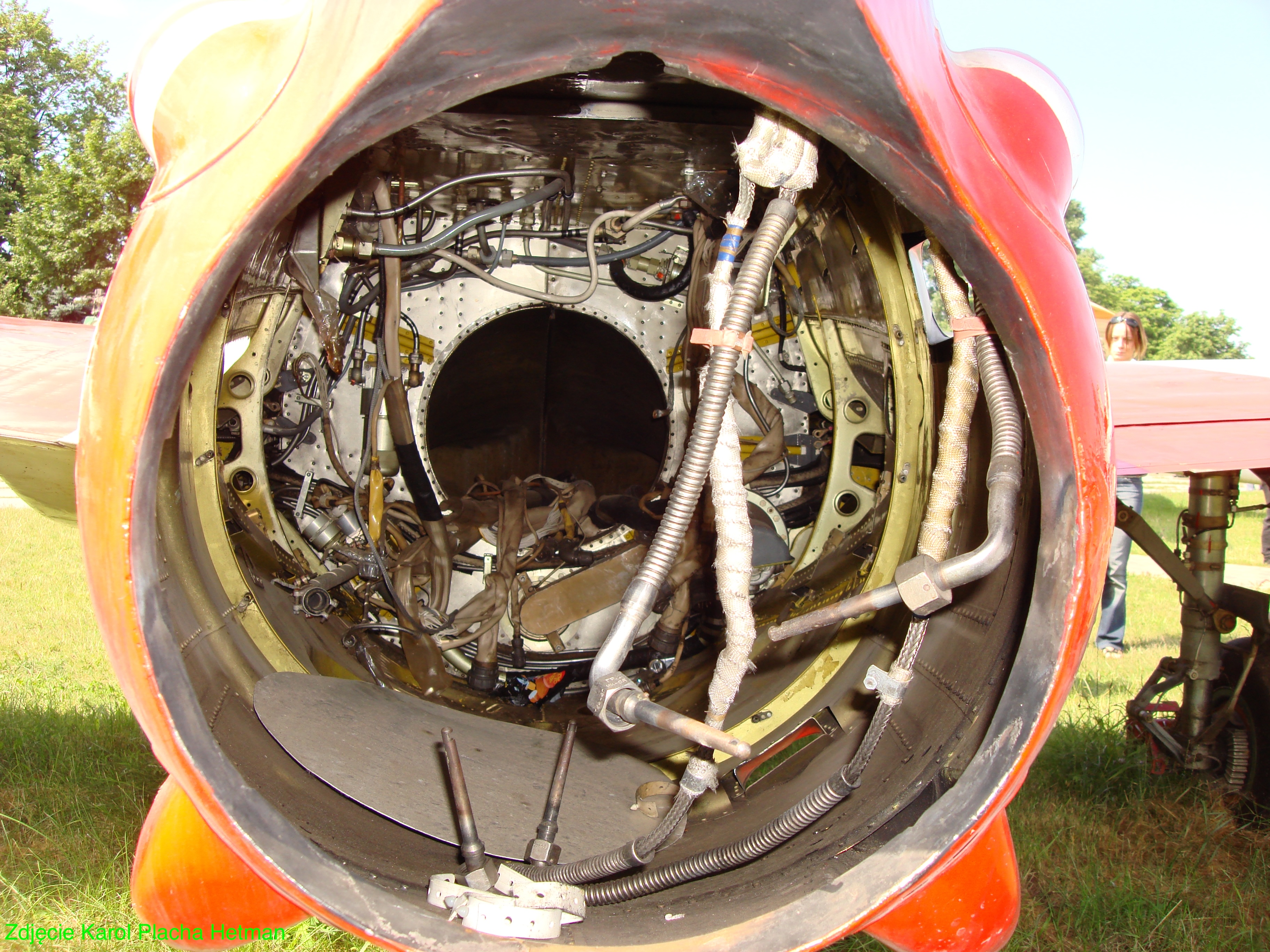
The aircraft's fuselage has a redan arrangement. It has a semi-monocoque structure in the middle and rear parts. The front part of the fuselage is made of a light spatial truss made of steel sections connected by welding. The truss is mounted to the first frame using 4 fittings. The front part houses the front landing gear compartment, the cannon and most of the avionics equipment. There are generators, batteries, oxygen cylinders and more. The cannon is placed on the right side and its ammunition on the left. There is a camera gun on the nose. The whole thing is covered with a cone made in one piece of epoxy laminate. The cone is slid on from the front along guides.
The actual part of the hull is made of a semi-monocoque structure made of light alloys. Mainly duralumin. It consists of 31 frames. There is a cabin compartment between frames 1-12. The cabin is hermetized, air-conditioned and ventilated. The cabin glazing consists of a fixed windbreak, with one window made of 10 mm thick organic glass. The windbreak is located between frames 1-4. The fairing has a metal frame and two windows with 8 mm thick organic glass. It is lifted up by an angle of 45 degrees using a hydraulic-pneumatic jack mounted behind frame no. 12. In the closed position, it is held by 8 locks. Sealing is done by a rubber sealing tube. Between frames 6-7 and 11-12 there are guides for the front and rear ejection seats, respectively. In the event of an emergency exit from the aircraft by the crew, the cabin canopy is thrown down and the seats are launched using a powder charge. Above the headrests are metal shields to pierce the cabin glass should it not be ejected before the seats are fired. The crew seats are separated by an internal 10 mm thick organic glass pane, protecting the co-pilot in the event of a seat failure in the first cabin. The seats are tilted back by 20 degrees from a line perpendicular to the fuselage axis.
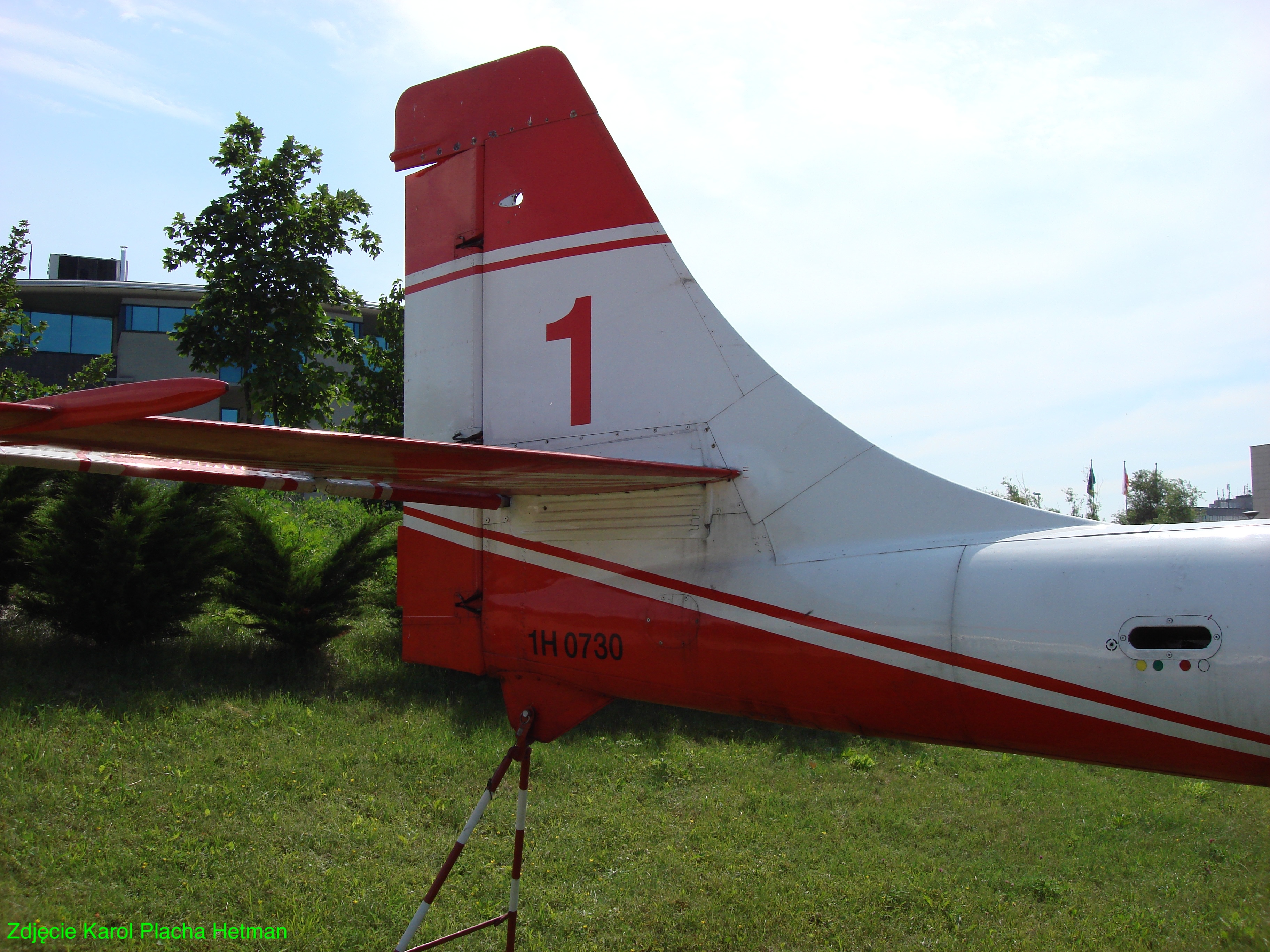
Between frames 12-17 there is a compartment housing the so-called rubber fuel tank, with a capacity of 500 liters. Access to the tank is through a sight glass located in the upper part of the hull, in the cover of which there are hatches for the fuel filler and fuel gauge. The front spar mounting the wings was placed at the height of frame 12, while the rear spar was placed at the height of frame 15. At the same time, these frames form the structure of the air inlet and the profiling of the wing-fuselage transition. Between frames 16-22 there is an engine compartment, ending with an exhaust nozzle. Very easy access to the engine is provided by removable covers on both sides. The skeleton of the rear part of the fuselage is formed by frames No. 18-31, with the first element of the tail boom being frame No. 23. On the starboard side, between frames 24 and 25, there is an EKSR-46 signal missile launcher. There is a tail on the extension of the beam. The front and rear spars of the vertical stabilizer are frames no. 27 and 30, and between them, a bumper with a mounting for anchoring the aircraft protrudes beyond the outline of the beam.
The empennage is in a classic cross-shaped arrangement and has a semi-monocoque structure. The vertical stabilizer with an arcuate leading edge and a rectangular rudder is an extension of the tail boom. The strength of the stabilizer is provided by frames 27 and 30, three spars and ribs. The rudder, with a maximum deflection angle of 27 degrees, is attached along the trailing edge with three fittings. It is aerodynamically loaded and mass balanced. The end of the ballast made of laminate houses the position light. The floating type horizontal stabilizer is adjusted in flight by an electric jack by an angle of 4.5 degrees up and 1.5 degrees down. It is composed of a front and rear spar, a center beam, 12 ribs and 12 side members, covered with metal skin. The elevator with a semi-monocoque structure is attached to the rear spar with two fittings. It can be tilted 28 degrees up and 18 degrees down. At the ends of the stabilizer, anti-flatter masses weighing 2 x 2.05 kg are mounted on booms.
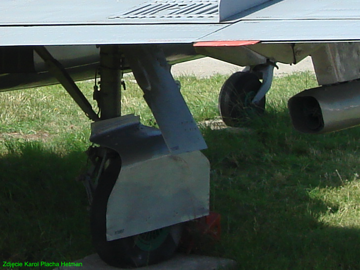
Three-support landing gear with a nose wheel, retracted during flight using a hydraulic system and released in an emergency using a pneumatic installation. The design and tires allow the aircraft to be operated from land airports. The main landing gear legs are attached to the spar in the wing and also serve as oil-air shock absorbers. In the open position, they are blocked with struts. When retracting, the legs fold into a recess in the wing, while the wheels fold into a chamber in the air intake housing. The whole thing is covered with three covers. The main wheels with a 600 x 180 tire are filled with air at a pressure of 0.54 MPa. Disc brakes activated by a hydraulic or pneumatic system in the event of a failure of the main system. The front leg wheel with dimensions of 380 x 150 and a tire pressure of 0.34 MPa is self-aligning in the direction of rolling of the aircraft. The nose landing gear retracts in the direction of flight into a compartment built into the front fuselage truss.
TS-11 control system.
The control system is of the rigid type. The deflections of the control stick are transmitted to the elevator and aileron via pushers, levers and rockers. The drive consists of hydraulic amplifiers that reduce the forces on the control stick. To maintain a proportional increase in force when the control sticks are deflected, a force simulator and hydraulic dampers are built into the system. The movements are transferred to the helm using drag lifts from the first or second cabin. The foot controls, connected by a quick-disconnect pusher, are adjustable depending on the pilot's height. The horizontal stabilizer has a variable wedge angle to balance the aircraft longitudinally at constant flight speeds. Its angle is controlled using an electric jack. The two-slot flaps on the wings are extended to three possible positions using hydraulic jacks. Flap control buttons are located on the left consoles in the first and second cabins.Silnik TS-11.
The power unit of serial aircraft is a compressor-turbine jet engine manufactured in Poland. The assumed minimum total service life of the HO-10 engine for aircraft from the third series was 600 hours and 100 hours of work on the ground, with a major overhaul expected after 300 hours in the air (with a tolerance of 50 hours). Short service life, high failure rate and insufficient performance completely disqualified this drive unit. As soon as it was possible, all aircraft of the first three series received target SO-1 engines. Over time, aircraft in active service were gradually replaced with SO-3, and in the 1980s, the SO-3 W engine with greater thrust was introduced. The total service life of SO-3 W was 1,200 hours, and SO-3 1,600 hours. The SO-3 W engine was factory-installed on the last three series of aircraft, and, depending on needs, on older units, e.g. those belonging to the Biało-Czerwone ISKRY Aerobatic Team.
The SO-1/SO-3 engine is equipped with a seven-stage axial compressor with an air flow of 18 kg/s. It consists of a rotor and a body with a set of vanes. The evaporative annular type combustion chamber contains a glow tube, cowl and 24 vaporizers, supplied with fuel by 12 service jet injectors, 6 starting injectors and 2 high energy spark plugs. The turbine is single-stage reaction. It consists of a rotor, a set of vanes, a partition and a cover. The outlet nozzle has a central cone and an outlet cross-section adjustable with inserts.
The lubrication system consists of a circulating and open system, using SDF-32 or AW-30 synthetic oil. The solution used enables long-term operation of the engine in inverted flight. The engine is started electrically using a starter motor that draws energy from the on-board battery or airport power source. The engine's propellant is JET A-1 aviation kerosene. Estimated fuel consumption of the SO-3 engine is 300 l/h. on the ground and 700 l/h in air.
The fuel installation consists of four tanks with a total capacity of 1,200 liters (996 kg of fuel). The soft main tank with a capacity of 500 liters is located in the hull between frames 12-17. Below it there is a soft-type rainwater tank with a capacity of 70 liters. The wing caissons house integral tanks with a capacity of 2 x 315 liters, sealed with special plastic. In order to ensure proper operation of the installation in flights at high altitudes, the free space in the tanks is filled with air with an overpressure of 0.13 kG/cm2. First, the wing tanks are emptied. Fuel is taken directly to the engine from the service and return tank, which is connected to other lines with one-way valves. In emergency situations, the fuel supply to the engine is cut off with a fire-fighting valve. The installation specifies a fuel reserve of 120 liters, necessary for a safe arrival to the airport, indicated by a light in the cabin. It allows for 8 minutes of flight at cruising speeds. The fuel system enables a 40-second inverted flight, i.e. on your back. Main components: tanks, valves, flow meter, fuel meter, suction-pressure unit, overpressure installation.
TS-11 equipment.
Plumbing installation.
Using electro-hydraulic distributors, the installation controls the retraction and extension of the landing gear, the deflection of wing flaps and air brakes. Additionally, it is used to raise and lower the canopy, operate the main wheel disc brakes, and power the aileron hydraulic boosters. The working pressure of the hydraulic system is 100 - 140 kG/cm2. The working fluid is AMG-10 or ASF-41 oil collected in a 6.5 liter tank. Main components: hydraulic tank, hydraulic pump, automatic unloading valve, hydraulic tank, safety valve, actuators, pressure transmitter, pressure gauges.
Pneumatic installation.
The pneumatic system includes the main and emergency systems. The main circuit is used to fill the cabin airtight line after closing the cover, power the anti-icing system and reload the gun. In the event of damage to the hydraulic system, the emergency pneumatic circuit controls the extension of the landing gear, flap deflection and braking of the main wheels. The operating pressure of the installation is 120 kG/cm2. The air is collected in two cylinders with a capacity of 2 liters each, and two with a capacity of 1.26 liters and 1 liter. They are filled from the airport installation through a common valve located under the laminate cover of the front of the fuselage. Main components: air cylinders, filter, check valves, pressure gauges, reducers.
Anti-icing installation.
It is used to chemically remove the layer of ice that accumulates on the windbreak in various flight conditions. For this purpose, ethyl alcohol is sprayed onto the outer surface of the windbreak using air from the pneumatic installation. A 1-liter cylinder stores spirit at a pressure of 3 kG/cm2. It is located under the laminate cover at the front of the fuselage. The installation is activated by a special button in the pilot's cabin. Main components: electro-pneumatic valve, reducer, tank, manifold, two check valves.
Fire protection installation.
It includes an electric circuit that activates the fire alarm system on board and an installation that delivers compressed carbon dioxide stored in two cylinders with a capacity of 4 liters each at a pressure of 150 kG/cm2 to the endangered place. The fire alarm circuit includes: thermal alarms, a relay, two warning lamps, a control button. The extinguishing circuit includes cylinders, pyro-heads, extinguishing buttons and collectors. The fuel system is equipped with an installation that cuts off the fuel supply in the event of a risk of ignition.
Air conditioning and oxygen installation.
The installation ensures appropriate pressure and temperature conditions in the cabin regardless of the flight altitude and ambient temperature. Air into the cabin is supplied from the engine compressor. Up to an altitude of 2,000 m, the pressure conditions in the cabin are the same as those in the surroundings. As altitude increases, cabin pressure increases smoothly and automatically. Up to an altitude of 8,000 m, the installation maintains a constant overpressure in the cabin of approximately 0.3 kG/cm2. The crew is additionally equipped with oxygen masks powered by the installation in the form of cylinders with a capacity of 10 liters of oxygen compressed at a pressure of 150 kG/cm2. The oxygen supply for both crew members allows for a 100-minute flight.
Electrical installation.
Depending on the type of equipment, three types of voltage are used. To power electric motors, electromechanisms, engine units, control devices, converters, lighting network (signal lights, landing spotlight, on-board instrument lighting), battery charging. The voltage of 28.5 V DC is used, the source of which is the GSR-ST-6000A starter with a power of 6 kW. The radio equipment draws energy from two PO-500-II converters producing single-phase alternating current with a voltage of 115 V/400 Hz. The truss of the front part of the fuselage houses the PT-125C and PAG-1F three-phase alternating current 36 V/400 Hz generators, powering the compass and the artificial horizon. Under the laminate cover there is also a 12-SAM-28 lead-acid battery with a voltage of 24 V and a capacity of 28 Ah, providing emergency power.
TS-11 cockpit equipment.
It includes a set of pilot and navigation instruments in the student and instructor cabins. They are arranged on the main board (flight and on-board equipment control indicators, clocks) and on the side panels, which contain switches, controls for the engine, generators and installations. The pilot and navigation equipment includes the following instruments: AGI-1 or AGD-1 artificial horizon, Mach number indicator M-095, KUS-1200 speedometer, WD-12U altimeter, UW-57 radio altimeter indicator, EUP-46M turn indicator, WRm variometer -30, GIK-1 gyroinductive compass, KI-13A magnetic compass.
The plane is controlled using a classic control stick and drag levers, while the engine control lever is located on the left side panel. The instructor's cabin is equipped with the necessary devices to control the student's actions.
Radio station.
R-800, and from 1985 R-802.
An ultra short wave (VHF) radio station allows you to maintain radio communication between ground radio stations and other aircraft in the air. The radio station (R-800 and R-802 W) consists of a transmitting and receiving unit located on the front truss, a set of controls in the cabin and a quarter-wave sword antenna on the spine behind the pilot's cabin. The range of the radio station is up to 120 km at an altitude of 1,000 m and 350 km at an altitude of 10,000 m. It has a frequency range of 100 - 150 MHz. The radio stations are coupled to the SPU-2 or SPU-2P on-board intercom, intended for internal communication between crew members.
Radio altimeter.
Radio altimeter – RW-2, later RW-UM.
The radio altimeter is designed to measure the actual flight altitude relative to the earth's surface. It works by measuring the return time of a wave reflected from the ground. The RW-UM radio altimeter commonly used on the TS-11 consists of a transmitting and receiving block (on the truss), the UW-57 altitude indicator, switches and a receiving and transmitting antenna. The antennas are placed under the fuselage in laminate covers in the shape of an inverted letter T. The first one at the nose of the plane is the transmitter, the second one is the receiver. The RW-UM radio altimeter allows you to measure the flight altitude above the ground from 0 to 600 m with an accuracy of 8%. The device's indications are misleading when the aircraft tilts in relation to the longitudinal axis by an angle exceeding 40 degrees. The crew can set the dangerous altitude value in the range of 50 - 400 m, signaled in the cabin by a red light.
Radio compass.
Radio compass - ARK-5 later ARK-9 or ARL-1601.
The radio compass is used to perform flights according to a ground-based radio transmitting station called a radio beacon. Based on signals sent from the beacon, the radio compass allows you to determine the aircraft's position, drift angle and wind direction, and enables instrument landing. The ARK-9 radio compass is commonly used in airplanes, the range of which at an altitude of 1,000 m is 160 - 180 km (at the beacon power of 500 W). The frequency range is 150 – 1,300 kHz on four sub-ranges. The radio compass works on the principle of cooperation of two antennas: a straight (non-directional), which takes the form of a strip placed on the upper part of the instructor/navigator's cabin cover, and a frame (directional) one on the front truss.
Tag receiver.
Beacon overflight indicator – MRP-56.
The marker receiver is used to signal the flight over DRL (distal airport radio beacon) and BRL (near airport radio beacon). The MRP-56 and MRP-56 P placed on the front truss were used on TS-11 aircraft. The device has a sensitivity of 1.5 - 4 mV and receives signals at a frequency of 75 MHz.
Identification system.
Responding device – identification.
Rescue system.
The basic rescue equipment are ejection seats, which allow for emergency exit from the plane. The recommended catapulting altitude in horizontal flight is 600 m, in diving flight 1,000 m, and the minimum altitude is 250 m. The pilot is fastened to the seat with hip, back and crotch belts. The parachute is located in the seat cushion. The detonation of the PK-4-1 pyrocartridge causes the seat to be launched along guides that provide it with the correct flight path. The pilot is separated from the seat manually by unfastening the seat belt buckle or automatically (AD-3 automatic) after 3 seconds at the latest. The parachute opens manually or automatically using the KAP-3 automatic device. It is permissible to deploy the seat with the cabin cover closed.
TS-11 armament.
The permanent armament is a 115 P or 150 P 23 mm cannon mounted in the front part of the hull on the right side. The magazine with a supply of 40 rounds is located on the left side. A shell collector is usually mounted on the side of the hull. The central part of the nose is occupied by a photo gun. The ASP-3 NM-1 gyroscopic shooting sight is used for aiming. There are 4 nodes for suspended weapons under the wings. Each node has a load capacity of 100 kg, i.e. the aircraft's load capacity is 400 kg. Typical weapons include containers with e.g. p-class Mars-4 or Zeus-1.
Reconnaissance system.
Iskra bis DF was equipped with three AFA-39 cameras. They are located on the engine air intake covers and in the dome under the right side of the fuselage.
T-T data of the PZL TS-11 Iskra TS-11 bis B aircraft, 1963.
Dimensions, span 10.06 m, length 11.25 m, height 3.50 m, load-bearing area 17.50 m2. Curb weight 2,560 kg. Total weight 3,734 kg. Maximum speed 720 km/h. Climbing speed 11 m/s. Landing speed 150 km/h. Range 450 - 1,250 km. Ceiling 10,000 m. HO-10 engine, thrust 1 x 7.84 kN. Crew: 2 people.
T-T data of the PZL TS-11 Iskra TS-11 bis B plane, 1969.
Dimensions: span: 10.06 m. Length: 11.25 m. Height: 3.50 m. Load-bearing area: 17.50 m2. Curb weight 2,560 kg. Total weight 3,734 kg. Maximum speed 720 km/h. Climbing speed 14 m/s. Landing speed 150 km/h. Range 460 - 1,250 km. Ceiling 11,000 m. SO-1 engine, thrust 1 x 9.80 kN. Crew: 2 people.
T-T data of the PZL TS-11 Iskra TS-11 bis DF aircraft. 1974.
Dimensions: span: 10.06 m. Length: 11.25 m. Height: 3.50 m. Load-bearing area: 17.50 m2. Curb weight 2,565 kg. Total weight 3,724 - 3,787 kg. Maximum speed 770 km/h. Cruising speed 600 km/h. Climb speed 19.4 m/s. Landing speed 183 km/h with a mass of 3,500 kg. Range 1,260 - 1,460 km. Ceiling 11,500 m. Takeoff run 650 m. Landing roll 710 m. SO-3 engine Thrust 1 x 1,100 kG. Crew: 2 people.
Written by Karol Placha Hetman