Kraków 2022-01-31
History of steam locomotives in the 19th century.
Part 04. 2022 year.
Further development of steam locomotives.
From 1850, steam locomotives with three coupled axles, i.e. the C system (in Poland, the designation Th), became the standard. From 1870, freight steam locomotives with axles in the system of four linked axles, i.e. the D system (in Poland, the designation Tp), appeared. Freight steam locomotives had high tractive force for two main reasons: The entire mass of the steam locomotive rested on the driving wheels, and the driving wheels were smaller in diameter. These locomotives were strong, but they did not develop high speed.
At the end of the 19th century, larger and larger boilers meant that steam locomotives with the 1'D axle system (Tr in Poland) or E (Tw in Poland) began to be built. An example of such a locomotive was the Austrian kkStB170, in PKP type Tr11, which we described in the previous chapter.
It is assumed that the 2'B axle system was typical from 1850 on the US railroad and has the American designation there. Then it was adopted in Europe. In Poland, the designation of the type Od and type Pd. From 1860, the 1'B or 2'B layout became the standard for passenger and express steam locomotives in Europe. An additional front axle was used to improve the running of the locomotive, so that it did not poke around the track. The drive wheels were large in diameter to achieve high speed. The diameter of the wheels sometimes exceeded 2.00 m. From 1920, freight steam locomotives in Poland received wheels with a diameter of up to 1.45 m, and fast locomotives from 1.85 m.
What is the reciprocating speed per minute in a steam locomotive engine? Simple calculation: If the diameter of the driving wheel is 2 m, the circumference of the wheel is 6.28 m. So one revolution of the wheel is the entire one cycle of the steam engine in reciprocating motion and the distance traveled is 6.28 m. For the steam locomotive to cover a distance of 100 km. , the wheels must turn 15,926 times. As we assumed that the engine ran 100 km in one hour, the engine performed 265.3 reciprocating cycles in one minute. With a smaller diameter of the wheels and the speed of 100 km / h, there will be more cycles. The steam engine of the locomotive can reach a maximum of 350 cycles per minute. Higher speed cannot be achieved because the properties of steam will not allow it.
Since 1870, it has been noticed that steam locomotives in mountainous terrain must have specific characteristics. For example: more traction, shorter extreme axle distance, running speed up to 60 km / h. Therefore, for mountain routes, steam locomotives with three linked axles were built, i.e. the C system, and later D. From the beginning of the 20th century, also the express and passenger steam locomotives had a standard 2'C axle system (in Poland Pk and Ok), and sometimes 2'C1 ' (in the USA the Pacific system, in Poland Pm and Om). The steam locomotives with such a system reached speeds of 120 - 175 km / h.
Wheels in a steam locomotive.
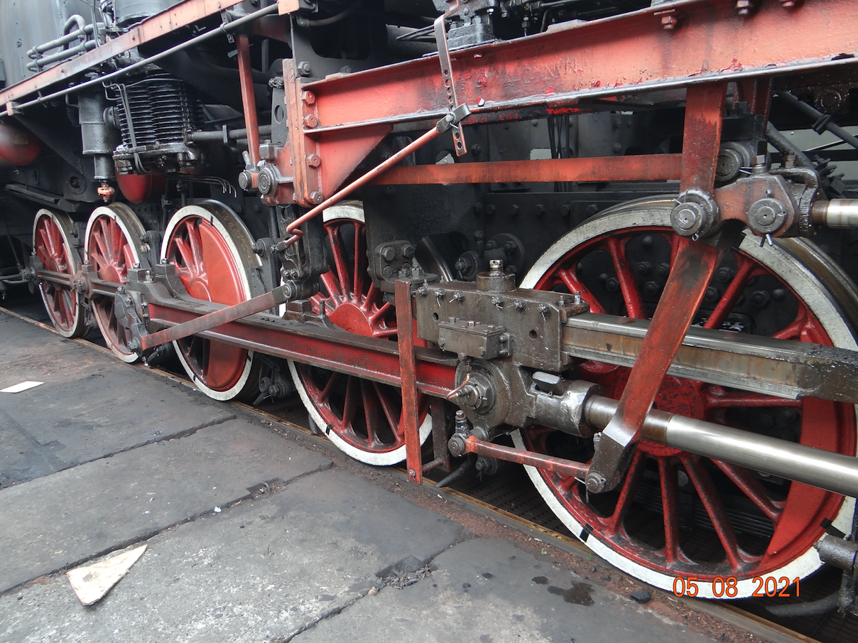
The drive wheels are most often spoked, less often disc or box-type, with two pressed discs with holes. The latter were used, for example, in England. When the three-axle system (C-system) was used, often the wheels on the second axle had a tapered flange to make it easier to negotiate curves. There were also solutions where the middle axis did not have flanges. The wheel axles were usually made of hollow cylinders. This reduced weight and increased endurance. But during the war, non-hollow axles were often made to speed up the production of steam locomotives. Masses (weights) were used in the drive wheels to balance the wheels loaded with mass from connecting rods and trusses.
The furnace in the boiler.
The size of the hearth (grate) is indirectly related to the wheels. The larger the wheels, the more elongated the grate to fit between the wheels. This made it difficult to properly fill with coal. It was best in small steam locomotives with low-capacity boilers and fast steam locomotives, where the last axle was tied in front of the hearth and the grate could be wide. For example the Pt47 steam locomotive.
A grate with an area of up to 3 m2 can be placed between the plate girders of the refuge. The grate is up to 1.25 m wide. If the grate surface is to be 6 m2, the length would be about 5 m. Such a grate cannot be properly filled with coal. Therefore, the hearth rises above the sanctuary. Practice has shown that good coal backfilling can be achieved up to 2.5 - 2.8 m in length.
In order to backfill the large and long grate well, a feeder was developed, which was called the stoker. The success of the stoker was, however, only half. In Poland, stokers were installed in some types of steam locomotives, and only in some of them. Practice has shown that an experienced smoker is better able to fill the grate than a mechanical feeder. Especially with poorer grades of coal. Therefore, after a few years, the stokers were usually dismantled.
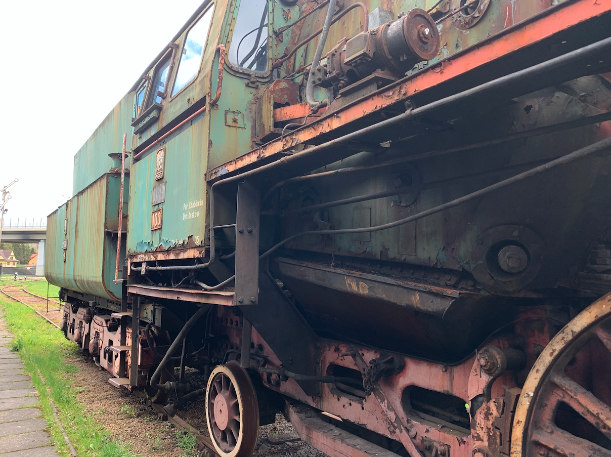
Description of the photo: In the Ol49-100 locomotive, the firebox protrudes beyond the sanctuary and the locomotive's driving wheels.
Steam engines.
In steam locomotive engines, double-acting cylinders are used, in which the steam pressure presses the piston alternately on both sides, enabling its reciprocating movement, without idle strokes.
An essential part of the engine is the steam distribution (also known as a steam distribution or stator) which controls the opening and closing of the engine's steam inlet and outlet channels. The timing gear injects steam from either side of the piston in succession and discharges the used steam. The order of opening and closing the channels determines the driving direction of the locomotive. The most widely used was a slide timing gear in the engine slide box. The slider opened and closed the steam inlet and outlet to the cylinder. Initially, the sliders were flat, but with increasing pressures, piston sliders began to be used. Several design solutions were developed, named after the names of their designers.
Initially, the locomotives had twin engines. They were two-cylinder engines with simultaneous steam supply to both cylinders, with the connecting rods offset by 90 degrees. This type of engine remained the dominant engine until the end of the steam locomotive era. Despite the addition of a third or even a fourth engine, the two cylinder engines were more economical and easy to operate. They are single expansion steam motors.
In 1876, a double expansion coupled engine was developed. The engine was developed by engineer Anatol Mallet. A coupled engine is one in which the pressure in the diesel cylinders is first lowered, and then the process is repeated in subsequent cylinders with lower and lower pressure. The engine was coupled in systems with two, three and four stages of steam expansion. In 1886, engineer Alfred de Glehn used a four-cylinder coupled engine for the first time. Typically, the steam between the cylinders is heated in secondary superheaters. Compound engines are more efficient than single-stage steam expansion engines, but are more complex. Coupled engines dominated the propulsion of steamships (ships and ships), while less often they were used in steam locomotives, where lower fuel consumption did not compensate for the complicated construction and operation and higher repair costs. However, in some countries steam locomotives with this type of engine were operated. The locomotives operated in Poland with a coupled horizontal steam engine were: Oc1, Od2, Od13, Pn12.
The steam locomotive sanctuary.
The refuge of the steam locomotive is the basic structural element of the steam locomotive. All the basic elements of the locomotive are mounted to the refuge: the boiler, engines, driving and rolling wheels, the booth of the steam locomotive team, lighting, air tanks, compressors. In tendrzak type steam locomotives, also water and coal boxes. The refuges were made of thick steel sheets or profiles, which are connected with rivets, and in the 20th century, also by welding.
There is a cantilever at the front and rear of each stand. Buffers (buffers) and couplers (catches) are mounted to the endcarriage. The endcarriage also has connections for the following installations: pneumatic (braking), steam (heating system), electric (lighting and heating system). In a tendrzak type steam locomotive, both headcarriages are the same. In a steam locomotive with a tender, the endcarriages have a different system of connecting the locomotive with the tender.
In the nineteenth century, steam locomotives were built in such a way that there was a bridge around the boiler, or at least the staff could move for inspection or minor repair, even while the train was running.
Steam locomotive boiler chimney.
Initially, the chimneys were narrow and high. Such a chimney improved the chimney draft and facilitated the combustion of coal. When the used steam nozzle was installed in the chimney, the chimneys became lower. This pair improved the chimney draft.
In the second half of the 19th century, large spherical or funnel-shaped spark gaps were mounted on the chimneys of locomotives. The idea was to minimize the risk of fires at the tracks caused by sparks escaping from the chimney.
Auxiliaries.
For signaling purposes, steam locomotives are equipped with steam whistles, and in older designs with steam or pneumatic bells. In order to enable driving after dark, the steam locomotives were fitted with lighting. Initially, it was kerosene lighting. Then electric lighting. Electricity was generated by a turbogenerator, i.e. a generator moved by flowing steam. For braking, a mechanical brake was used, which was actuated by a shifting lever. Then the mechanical brake was actuated by a steam system. Ultimately, brakes acting on the jaws by means of a pneumatic system were used. The pneumatic system is filled with pressurized air by a compressor. There are air reservoirs in the brake system, the main one and often the auxiliary one. Increased air pressure in the braking system keeps the system unbraked. When the pressure drops, the jaws tighten on the wheels and the train brakes. The pressure drop is forced by the driver who actuates the brake tap lever.
W lokomotywach parowych w USA stosowano duży przedni lemiesz, który nazywano cowcatcher. Taki lemiesz skutecznie odrzucał na bok gałęzie i inne przeszkody które znalazły się na torach. W Polsce stosowano lemiesze dwuczęściowe. Po jednym nad każdą z szyną. Dolna krawędź lemiesza od szyny była odsunięta o około 10 cm.
Tender.
Tender is a type of wagon that carries a supply of water and coal to power a steam locomotive. The first tenders had a two-axle chassis system. In 1850, three axis tenders appeared. They were the standard for the great world war. Subsequently, four-axle tenders, usually mounted in two bogies, became standard. There were also a few designs of five-axis tenders. There were also atypical tenders with a steam condensation system to save water reserves.
In Poland, tenders were marked with: two digits, a capital letter and two or three digits. The first number is the amount of water taken up, for example 32 is 32 m3. The capital letter C stands for three axles in the chassis. The number 45 is 1945, and 202 is the American tendra type.
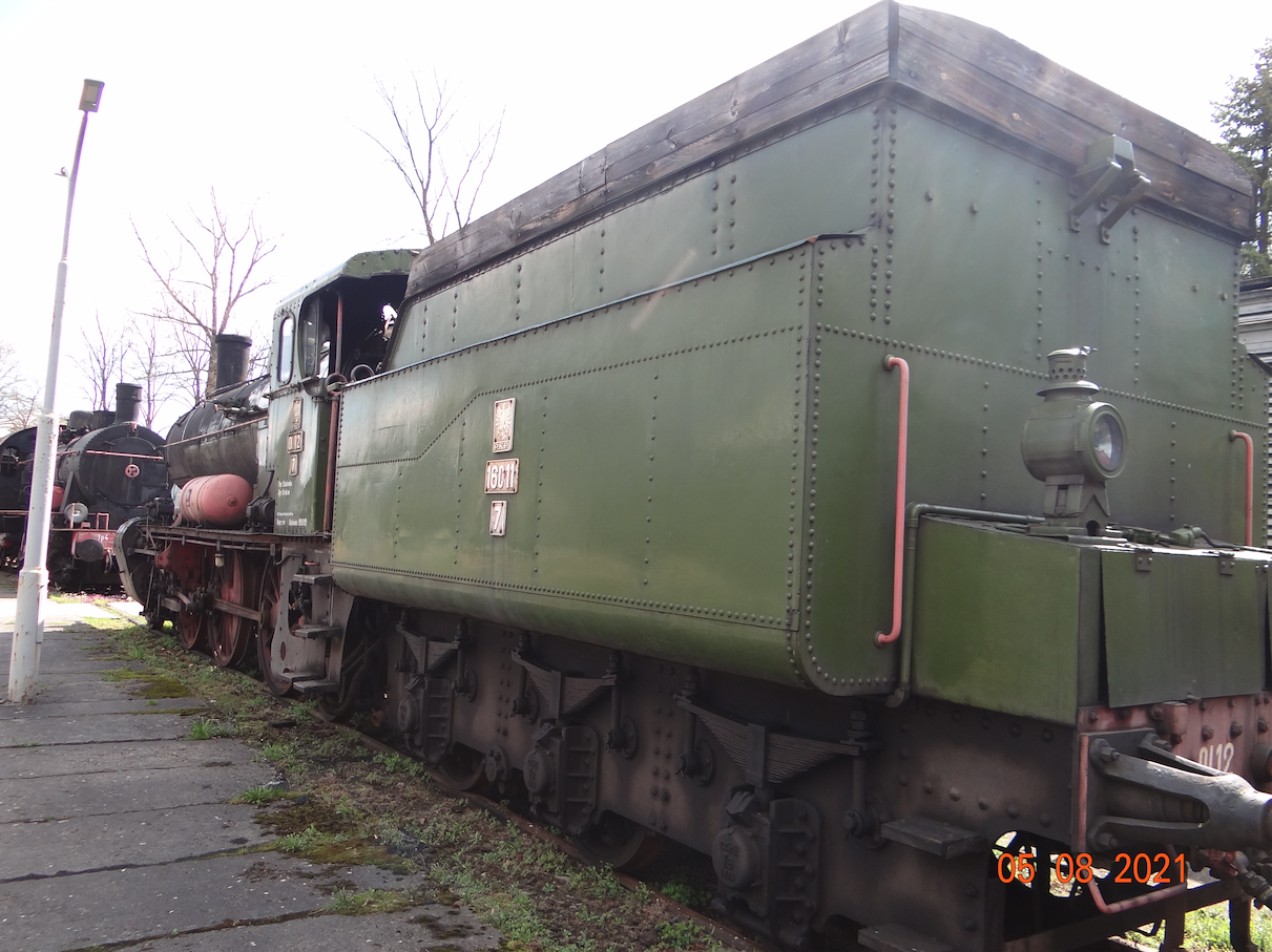
Description of the photo: A typical tender from the second half of the 19th century, type 16C11. It takes 16 m3 of water and 7 tons of coal. Tender is a three-axis, riveted construction. Leaf springs, plain bearings. In the back is a toolbox and oil lamps. Tender was built in Austria.
Written by Karol Placha Hetman