2020-08-11
Airborne ground-based radio finders.
Part 2.
Marek Kaiper
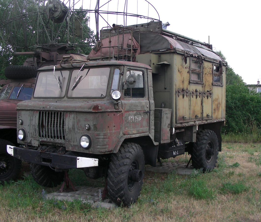
VHF ARP-6 and ARP-6D radio finders.
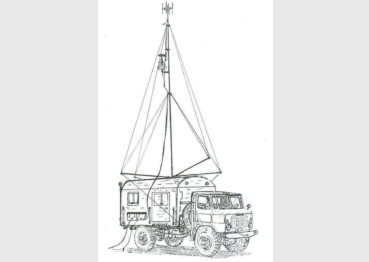
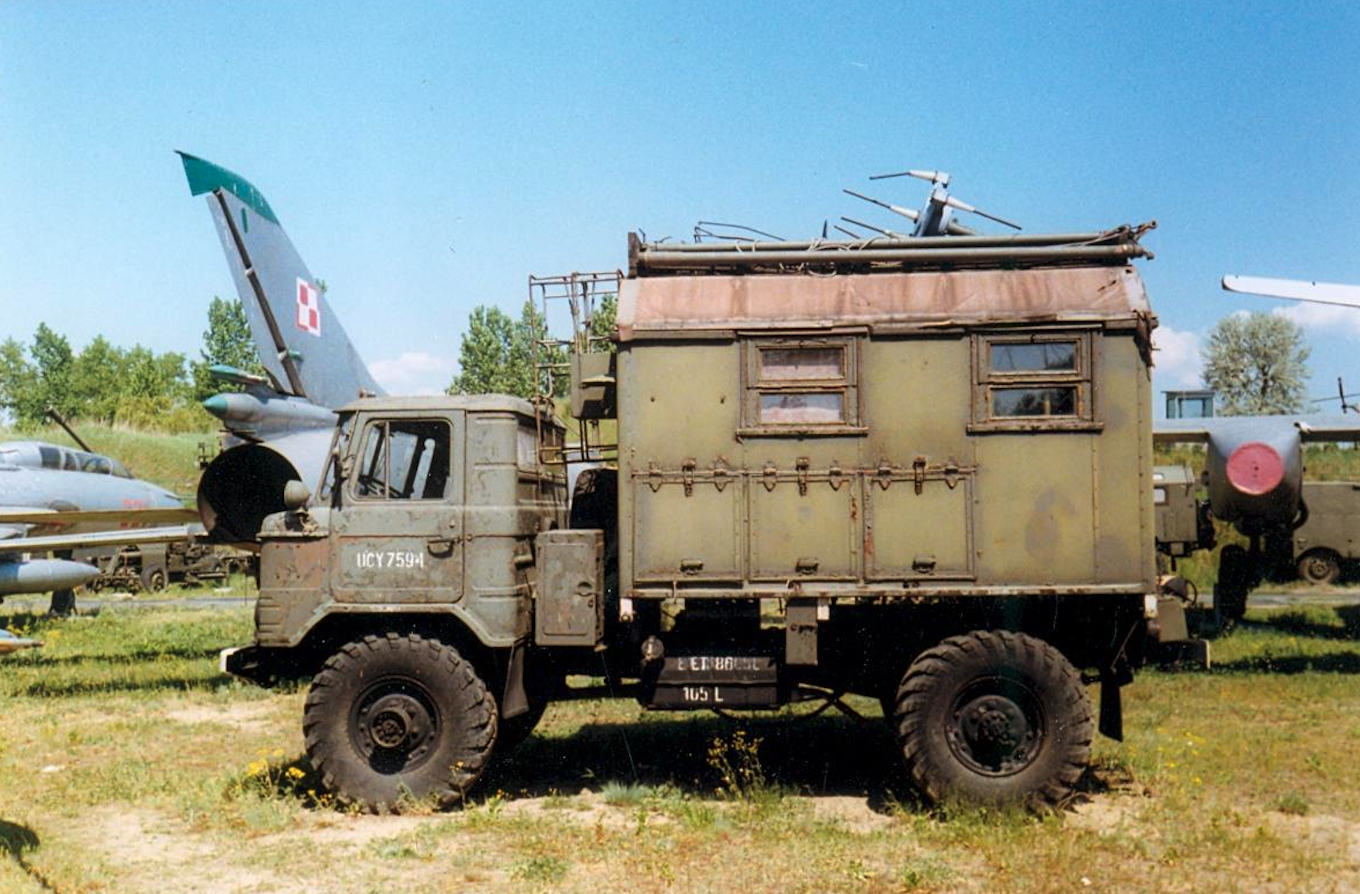
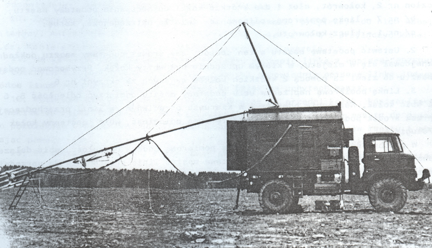
The two-channel ARP-6 radio finder was a completely new design compared to its predecessors. It was also mounted on the smaller GAZ-63 and later GAZ 66 with the KUNG-2 body. In Czechoslovakia, these beacons were mounted on 6x6 Praga V3S cars. It was the longest used type of radio finder in the Polish Air Force, from the first half of the 1960s to 1996, when one of the last ARP-6Ds at the 4th Air Base was missing. It was the longest-used type of radio finder in the Polish Air Force, from the first half of the 1960s to 1996, when one of the last ARP-6Ds at the 4th Air Base was missing.
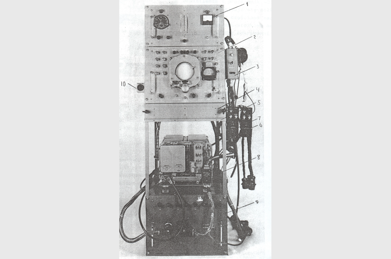
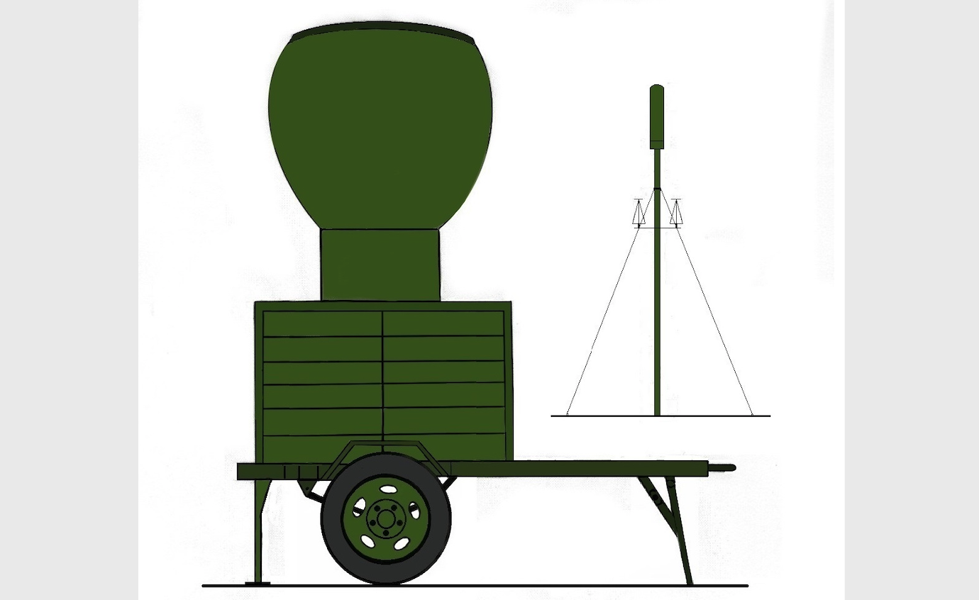
The antenna system consisted of two "H" type antennas (N-S and E-W) with straight dipoles having characteristics similar to eight and a geometrically placed straight central dipole with omnidirectional characteristics. The electromotive force induced in the antennas was proportional to the height of the antenna and the direction of the incoming signal. The phase difference between the signal from the N-S antenna and E-W is the bearing direction information. The ARP-6 was equipped with an R-801W VHF radio and an R-801W receiver for the second channel. The APP-6D uses two R-802W radios for the first and second channel. Another difference was the BK-9 second channel switching blocks, in the ARP-6 they used an electromechanical system, in the ARP-6D it was a tube electronic circuit. During the two-channel operation, the bearing line on the screen for the 1st channel was continuous and for the 2nd channel it was broken. Practically two-channel operation was used sporadically. In the drawer under the BP-3 main block (indicator), there was a permanently installed IKD device for selecting germanium diodes D-2W in the A-10 antenna head. It was enough to pull out the cables and screw them in place of disconnected cables. In this case, the ARP-6 indicator worked as an oscilloscope, enabling the selection of diodes in pairs. The WTK-1 (ARP-6) and WIK-1 (ARP-6D) portable indicators can be connected to the radio-finder with a four-core P-271M field cable with a length of up to 10 km. MIZ-10 wire tape recorders, MAG-8 tape recorders or Polish MAK-S tape recorders were used to record the correspondence. The PAB-2 artillery compass and the KIG control and measurement generator that could operate on one of the 11 available frequencies were used to orient the radio finder to the north. Power supply with 220 V 50 Hz voltage from the network or two AB-1 -0/230 generating sets and in emergency from the ZST-70PM battery bank via an automatically switching on PO-500 converter for a period of 30 minutes. It was enough to prepare and switch on the generator set.
Radionamiernik UKF ARP-9.
The two-channel ARP-9 radio finder was mounted on the UAZ-452 AE (minibus) with the GAZ-704 trailer. It was equipped with an AMU antenna system, 9 m high, with an antenna head similar to the ARP-6, set up 70 m from the shelter and the control generator antenna placed 0.8 - 8 m from the radio finder. It was equipped with TU-TS apparatus enabling remote control of the finder by sending 12 signals (commands) in the frequency range of 3 kHz-4.3 kHz from the control point and 6 signals with the frequency of 4 kHz-6 kHz from the radio finder to the control point. With their help, the radio finder was switched on and off remotely, the appropriate R-802 radio channel was selected, and the KIG control and measurement generator and the noise suppressor were switched on and off. Information on the operating status, breach of the security installation and telephone communication were sent from the radio finder. The remote control point consisted of a BPD dispatcher block, an IP actuator block and two IEMs equipped with electromechanical (pointer) indicators, one for each radio finder channel. Remote control signals could be sent via the P-274 cable over a distance of up to 12 km. Power supply 220 V 50 Hz from the network through the converter 50Hz / 400Hz or 220V 400 Hz from two generating sets AB-2-0 / 230 / Cz400.
Radionamiernik DMF ARP-10.
The two-channel ARP-10 radio finder, despite being equipped with two VHF / DmF R-832M radios, was intended to work only in the DmF band. The radio finder was produced in 3 versions: ARP-10-I and ARP-10-II on the GAZ-66 and ARP-10-III cars in the shelter placed on lifts. In versions II and III, the antenna with the driving column was mounted on the body of the EP-4 power station on a single-axle trailer, at a distance of 35 m from the shelter. In these versions, an additional radio finder antenna was placed on a 6 m high mast standing next to the shelter. Due to the difference in height between the two antennas, a higher accuracy of radio targeting was achieved. The radio finder was equipped with a permanent antenna of the KIG control and measurement generator set at a distance of 35 m from the main antenna (70 m from the shelter). Using the KIG device, you can systematically control the tuning of the beacon on 17 freely selected frequencies. The radio finder, like the ARP-9, was equipped with the TU-TS apparatus for remote control and with two portable indicators.
This radiometer works with the phasometric method. That is, measuring the phase shift between the RF voltage. received from the targeted aircraft and the reference voltage. The finder antenna consists of a stationary dipole and a reflector rotating around it. Thanks to this, the directional characteristic of the antenna has the shape of a rotating cardioid. The received signal is amplitude modulated with the frequency of rotation of the reflector. After processing, a sine wave is formed, the phase of which depends on the bearing on the plane. The sinusoidal reference voltage is created in the generator, the rotor of which rotates with the rotation of the antenna reflector. The radio finder is oriented so that when the antenna is rotated, when it coincides with the north, the reference voltage phase is zero.
ARP-10 was adapted to work with the RSP-6, RSP-7T, and RSP-10 radar landing systems in the event of switching to the DmF range in radio correspondence.
Power source: EP-4 power station on the IAPAZ-738 (1-P-1,5) trailer consisting of two AB-4-0-230 / Cz 425 generating sets. Power supply from a three-phase 220 / 380V 50 Hz network via AŁA-3.5 converter generating voltage 220V 427Hz.
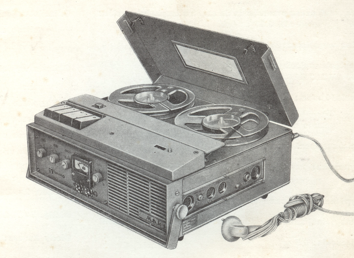
The MAK-S tape recorder comes in two sizes. It was the most widely used tape recorder on the ARP-6 and ARP-6D.
VHF / DmF ARP-11 radio finder (Je-512).
The two-channel ARP-11 radio finder was a radio finder for both aviation communication bands (VHF / DmF). It was equipped with two VHF / DmF R-863 radios. The frequency range is 100-149.975 MHz and 220-399.975 MHz. The range at an airplane flight altitude of 1000 m for the VHF range - 80 km and for the DmF range - 100 km. At the flight altitude of 3000 m, the range was 150 km for the VHF range and 180 km for the DmF range. Simultaneous bearings on 2 working frequencies were possible. Radio correspondence was recorded on two wire MS-61 recorders. The bearing was displayed on the digital indicator Je-512.06 (E-512-06) with two displays: the upper one for the 1st channel of the finder, the lower one for the 2nd channel, and on the indicator light indicating the bearing value analogically by means of a light on the scale surrounding both digital indicators. (36 signal lamps). The set consisted of two Je-512.07 gauges that can be set on the air traffic control tower or in the RSP landing system, including the MN-61 wire tape recorder. The portable indicators were connected to the TU-TS system enabling remote control of the radio finder. It allowed to send 34 control commands and send 12 control signals. Thanks to this, the finder could work without staff, giving the bearing from the command post. While working from the command post, it was possible to combine the radomachine signal from the Je - 512.07 indicator with the WISP-75 gauges of the RSP-10MN landing system in order to identify the calling aircraft. Cables connecting the finder with the haulage indicator caused many problems, therefore they were usually not laid.
The radio finder was mounted on the GAZ-66-05 car with the K-66N body and the IAPAZ-738 trailer. The antenna system consisted of the AMU-1 mast with the Je-519-2 antenna head placed on the roof of the body and the AMU-2 mast with the Je-519-2 antenna head located 100 m from the finder room. The antenna heads were equipped with 8 straight dipoles and a central dipole in the center. So 4 crossed H-type antennas. The radio finder could work only from the antenna on the roof of the body or from the aerial, and also from both antennas simultaneously. Working from two antennas reduced noise and interference. Orientation of the station to the north direction was realized by means of a portable Je-519-4 generator.
Power supply from 380 / 220V 50 Hz mains through two Je - 512 - 05 voltage stabilizers or from two AB-2-T / 230 - M1 generating sets. Emergency, for a period of 30 minutes, from a battery (2 6ST75EM batteries) with a voltage of 24V within 30 minutes or from a GSR-6000 generator driven by a shaft from the car's engine with a voltage of 27V.
Terrestrial airborne finders
Bibliography:
Automatic ARP-11 radio finder, technical description and operation, Warsaw 1986.
Avtomaticzeskie ukw ARP-4, ARP-5, ARP-1 radios. Description and instructions after the exploration, Moscow 1957.
Terrestrial and on-board radio navigation and aviation communications equipment, Poznań, 1972.
Flight insurance in the aviation of the armed forces of the Polish People's Republic, Poznań 1981.
Description and operation of the ARP-6 radio finder, Warsaw 1961.
ARP-6D radio finder, technical description and operation, Poznań 1977.
Knowledge of the devices of the aiming point, Flight Insurance Specialist Training Center, 1979.
Written by Marek Kaiper