2020-08-11
Airborne ground-based radio finders.
Part 1.
Marek Kaiper
Introduction.
A radio finder is a radio receiver designed to determine the direction (bearing) on a working radio station. Measured as the value of the angle between the direction of magnetic north and the direction of the radio station. Radio finders were used in maritime navigation and aviation for navigation and rescue purposes, and in land forces as an element of radio-electronic warfare. In sea navigation, they made it possible to obtain bearings for the beacons placed on the shore. These bearings, plotted on the map, were used to determine the position of the ship. Ship's radio finders worked on medium waves with a frequency of 263.5 - 325 kHz. In the times of the Polish People's Republic, Russian automatic ARP-50 and ARP-53 marine radar finders and Polish RADMOR OG-131 and ARC-1402 as well as MORS OK-102 radio receivers with a rotating antenna and a bearing scale measuring course angles were used. These receivers were tuned by ear to the minimum signal. The RADMOR OG-131 radio finder was equipped with a stationary antenna system consisting of 2 frame antennas and one rod antenna. The connection with the gyrocompass repeater allowed the bearing to be measured from the north direction. The automatic RADMOR ARC-1402 was one of the few marine radios showing both the bearing and the course angle digitally. So the angle between the ship's course and the direction of the working beacons. Nowadays, marine radar finders have replaced GPS devices.
The ground-based aerial radios were part of the USL-48 instrument landing system in all its versions, as well as the SP-1s and SP-2s systems. In aviation, the bearing given to the pilot by the operator of the ground radio finder was a reverse bearing, i.e. the bearing value of the working airplane radio was increased by an angle of 180 degrees. The reverse bearing is the value the pilot must take to return to the aerodrome (reverse bearing = straight bearing + 180 °). During short-wave aviation radio communication, PKW-45 stationary short-wave radio finders and R-301 car radios were used in the Polish Air Force aviation.
In Poland, until the beginning of the 1960s, on-board short-wave radio stations (RSI-3M1, RSI-4, R-805) were used in aviation communication, from the end of the 1950s the Polish air force switched to ultra-short wave communication (R-800 (RSIU-3M), R-801W (RSIU-4), R-802 (RSIU-5M)) and at the end of the 20th century the transition to the decimeter wavelength range (R-803, R-863) began. In the VHF band, ARP-4, ARP-5, ARP-6, ARP-11 series were used in Poland. Radio beacons were developed in the runway axis at a distance of 3500 m from its beginning and 500 m ahead of the further beacon, if the terrain conditions allowed it. Due to such a distant position, until the end of the 1960s the duty shift was armed with two submachine guns wz. 43 cartridges and two magazines with cartridges (70 pcs.), Then exchanged for the AK kbk. These weapons were passed on to each other on duty. The drafting soldiers were the operators of the radar markers.
VHF radio finders in the Polish Army aviation operated on the general tracking frequency (4th channel), the pilot, wanting to receive a bearing, switched the aircraft radio to the tracking channel and calling the appropriate radio finder with the code name, the determined signal "give me priboj", later asked for the bearing "give bearing". In response, he received the value of the bearing to the airport, given by a voice by the operator of the beacon. The codename of the radio finder was the codename of the airport with an added number 4, eg "Benzol 4". There was also the "polus" signal meaning the loss of geographical orientation, on which the operator of the beacon gave the pilot the bearing value, and then gave the pilot's index, bearing value and the time of its application to the command post (flight director). In the event of the "I am in danger" signal, the operator provided the flight manager with the pilot's index, bearing value and all information obtained from him.
The two-channel VHF radio finders could operate on the general tracking frequency of the 1st channel of the finder or on the assigned frequency of the 2nd channel. The beacons duplicated the aircraft crew's own tracking of the working beacon by means of a medium-wave automatic radiocompass. VHF ground-based radio finders could also track the emergency radio of the R-855 "Komar" pilot, which made it possible to determine the bearing of the pilot who left the plane in an emergency, 20-30 km from the radio finder. This required switching to channel 1 of the radio finder station.
Radar finders were also used in radar landing systems (RSP). The RSP-4 set was equipped with the ARP-4 radio finder, in the RSP-5 the ARP-5 radio finder, the RSP-6, RSP-7, RSP-10 systems were equipped with their own built-in automatic radio finder in the RSP-7 / RSP-7T ARP-7 in RSP-6M2 and RSP-10 ARP-7 / ARP-11. These radar finders were used to identify the aircraft. The circular surveillance radar operator (dispatcher's radar), eg DRŁ-7 of the RSP-7 system, saw several planes on the screen, he did not know which one was causing it. Turning on the finder and switching it to the DRŁ-7 indicator resulted in the formation of a radial bearing line on the screen indicating the calling aircraft. It was also possible to switch the indications to the PRŁ-7 landing radar indicator or to provide the bearing from its own indicator on the oscilloscope lamp of the radio finder. The ARP-7 was equipped with the A-10 antenna head of the ARP-6 radio finder. The new Russian RSP-27s radar landing systems and the mobile RSP-28 are also equipped with an automatic ARP-RS radar. The MRŁ-1G radar meteorological station was equipped with the PAG-1 storm indicator operating at 7kHz frequency, showing the location of lightning discharges.
Aircraft radios called automatic radiocompasses (ARK) are used in navigation to locate airport beacons. Structurally they differ from terrestrial radio finders with a frame antenna and a pointer indicator. Airplane navigation automatic radiocompasses operated in the frequency range ARK-9 150-1300 kHz, ARK-11 120-1340 kHz, ARK-22 150-1740 kHz, which was in the frequency range of ground beacons 150-1300 kHz for APR-7 and 150 -2000 kHz for RL 3301 "Krokus. Search and rescue radiocompasses ARK-U2 on the VHF range were used to indicate the direction to the second plane with which radio correspondence was conducted and they wanted to join it, and to find R-855 "Komar" personal air radio stations operating in the radio beacon regime on the 121.5 MHZ frequency or 243 MHz (R-855A2). Also in the Navy aviation, the rescue radiocompass DF-430 F scanning frequencies 121.5 MHz, 243 MHz and 406 MHz and CHELTON scanning frequencies 121.5 MHz, 243 MHz, 156.8 MHz, 406 MHz as well as ARK-U2 and ARK-UD (121.5 MHz). The Navy also used the A-100 radio finder to target hydroacoustic buoys for anti-submarine combat. The radio finder had 18 channels with their indicators on 18 circular lamps. Frequency range 49.2 MHz (channel 1) to 53.45 MHz (channel 18), after detecting a signal from the buoy on a channel, the appropriate lamp was lit, and after activating the "ARK" mode, the ARK pointer indicated the direction of the buoy.
Currently, in NATO aviation, ground-based airborne finders are not used, they are replaced by GPS and PRMG-4 or TACAN radio-technical navigation systems. In Russia, radio finders are still used in military (ARP-11, Je-553 Pichta 3 and Je 554 Pichta 4) and civil aviation. The latter for the 118-136 MHz band with 16 dipole antenna heads, ARP-75 (pointer indicator), ARP-80 (pointer - digital), ARP-95 (computer monitor), ARP-AS, ARP "Platan" and on 100-400 MHz band ADF-2000.
The only type of troops still using ground-based radio finders in Poland are the ground troops which use them to track enemy or spy radio stations. In the times of the Polish People's Republic, the Orieł-1M type Orieł-1M land radios were used on the GAZ-69, R-301 cars on two ZIL-157 and R-359 cars on two ZIL-157 and R-359M cars on two STAR-266 cars, R-363 on ZiŁ-157, TK-5 on two Ural -375 cars and two trailers.
PKW-45 and R-301 shortwave radio finders.
The PKW-45 stationary radio finder was a further development of the PKW-43 radio finder. The apparatus of this radio finder was placed in a small brick house built on a square plan. There was one antenna system antenna on each side of the house. So it was equipped with 4 dipoles (Adcoc system) placed on masts 12 m high. The houses were equipped with electric heating and parquet floors. After the withdrawal of PKW-45 radio finders, these houses for many years served as rooms for mobile radio finders or acted as an aggregation room for new VHF radio finders. The shortwave radio-finder PKW-45 operated at the frequency of 1.5 - 16.8 MHz. This range was divided into 4 sub-ranges: 1; 1.5 - 2.7 MHz; 2; 2.7 - 4.9 MHz; 3; 4.9 - 9.0 MHz; 4; 9.0 - 16.3 MHz. The bearings were provided by the operator using the shortwave radio RAF-KW-5 mounted on the GAZ-63 car. In the construction of the finder, 2K2M electron tubes (12 pcs), known from the war, were widely used. The locator operator determined the bearing to the aircraft radio by hearing (at the minimum signal).
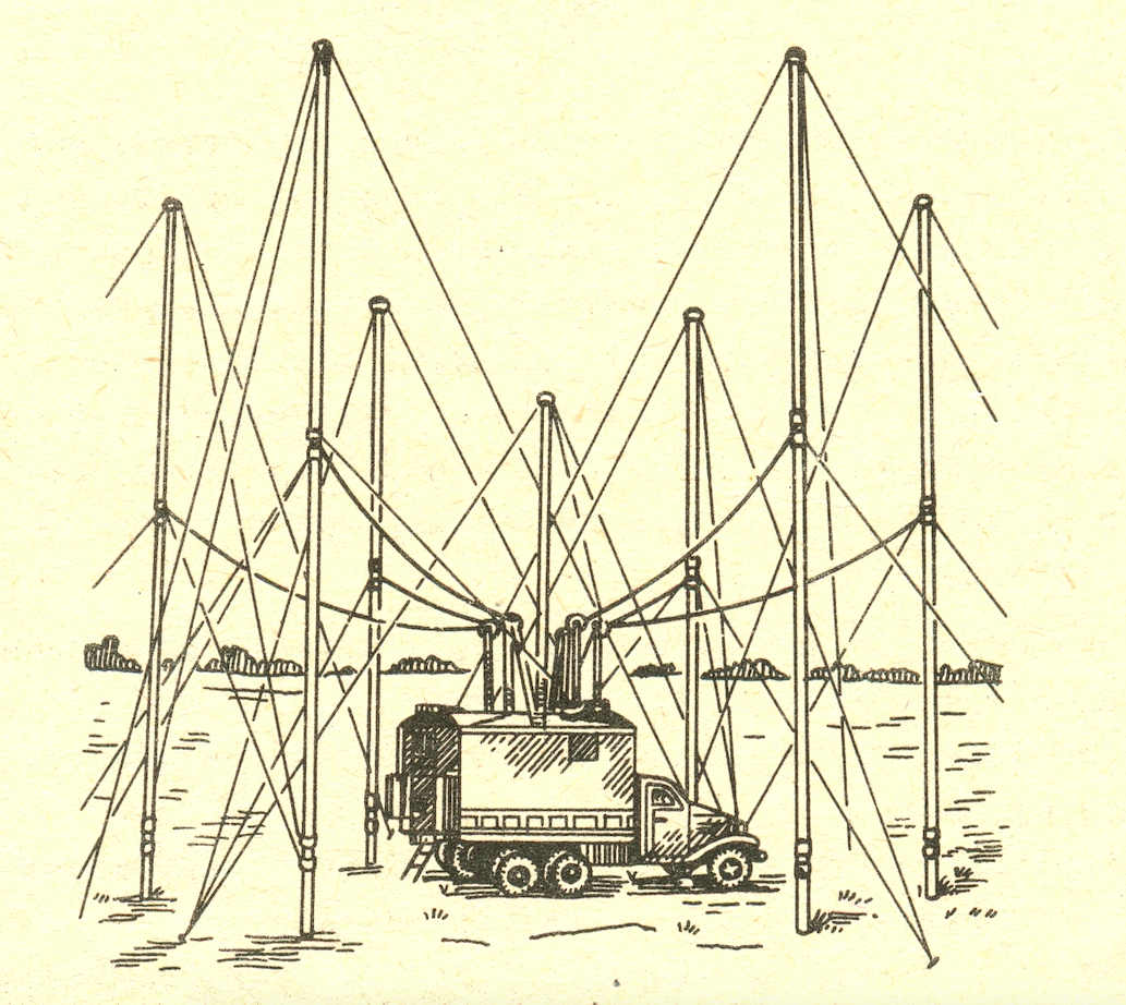
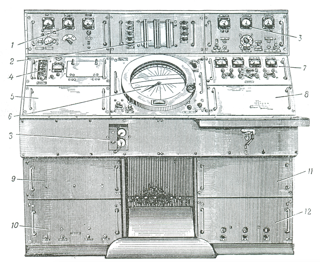
The last KF radio-finder used in the military aviation was the R-301 radio-finder adopted from the army (production started in 1948) with a frequency range of 1.5MHz-12MHz. These radar finders were not equipped with a correspondence radio. Communication with the planes was provided by an additional shortwave car radio, eg RAW-KW or R-820 (RAS-KW). The radio finder set was mounted on two ZiŁ 157 cars. One had a finder room, and the other had diesel electric units. The R-301 radio finder was equipped with 3 H-type antennas positioned omnidirectionally in azimuths of 30 °; 90 °; 150 °, 210 °; 270 ° and 330 ° and the antenna open (omnidirectional). The "H" type antenna dipoles were placed on masts 13 m high, the height of the open antenna 9.3 m. The signal from the "H" type antennas was sent to the goniometer coils. The goniometer transformed the three input signals into two signals fed to the deflection plates of the oscilloscope tube. The R-301A version was equipped with 4 H-type antennas, their dipoles spaced at 0 ° azimuths; 45 °; 90 °; 135 °; 180 °; 225 °; 270 ° and 315 °. In this version, the frequency range was 1.5-25 MHz. The bearing was visualized on the screen of the oscilloscope tube in the form of a diameter line. However, this display of bearing may be subject to an error of 180 °. The operator has a bearing on a working airplane radio station, but does not know which side of the bearing line the plane is on. In order to determine the page, one had to press the "PAGE" button on the goniometer's knob. After pressing the button, the time base line starts from the center of the screen towards the working airplane radio. The bearing on the working aircraft radio is obtained by turning the goniometer knob until the maximum diameter line is obtained on the screen of the oscilloscope tube. Bearing reading against the upper mark on the scale around the oscilloscope tube. The scale rotated as the goniometer knob turned. Additionally, the finder has the ability to determine the bearing to the hearing. By turning the goniometer's knob, the operator set it to the minimum signal heard in the headphones. Power supply with three-phase voltage of 230 V, 50 Hz network or from two 3EPZ-4 generating sets.
Probably the last R-301A radio-finder in the military aviation was deployed on the training ground of the Flight Insurance Service Training Center (OSSUL) in Grudziądz as early as 1966. Operator training was no longer carried out there.
VHF ARP-4 and ARP-5 radio finders.
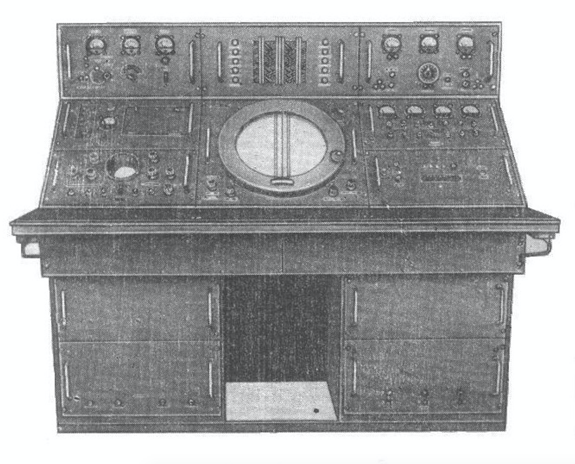
The transition of military aviation to the range of communication on VHF waves resulted in the introduction of new radio finders. They were completely automatic, which meant that the operator did not have to do anything to get the bearing line. The time base line (bearing) started automatically from the center of the oscilloscope tube screen when the remote control pressed the transmit button. The operator of the finder on this line guided the moving line of the board and read the appropriate bearing on the mechanical scale. The scale of the board was equipped with a movable diaphragm that made it possible to read a straight bearing (direction to an airplane radio station) or a reverse bearing (direction to a radio finder). The radio-finder cooperated with new VHF aircraft radio stations and was equipped with them (R-800 (RSIU-3M) and R-801 (RSIU-4)).
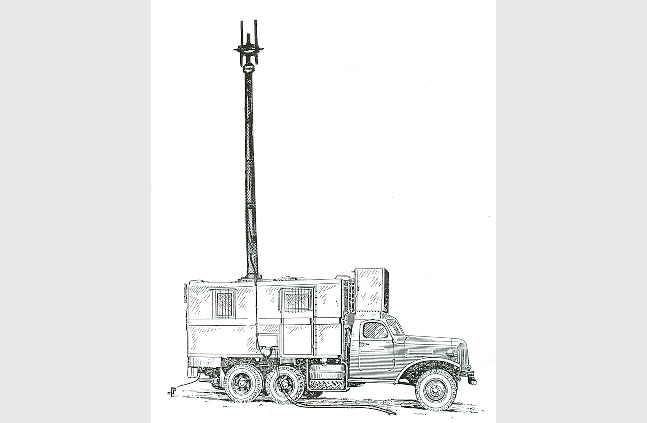
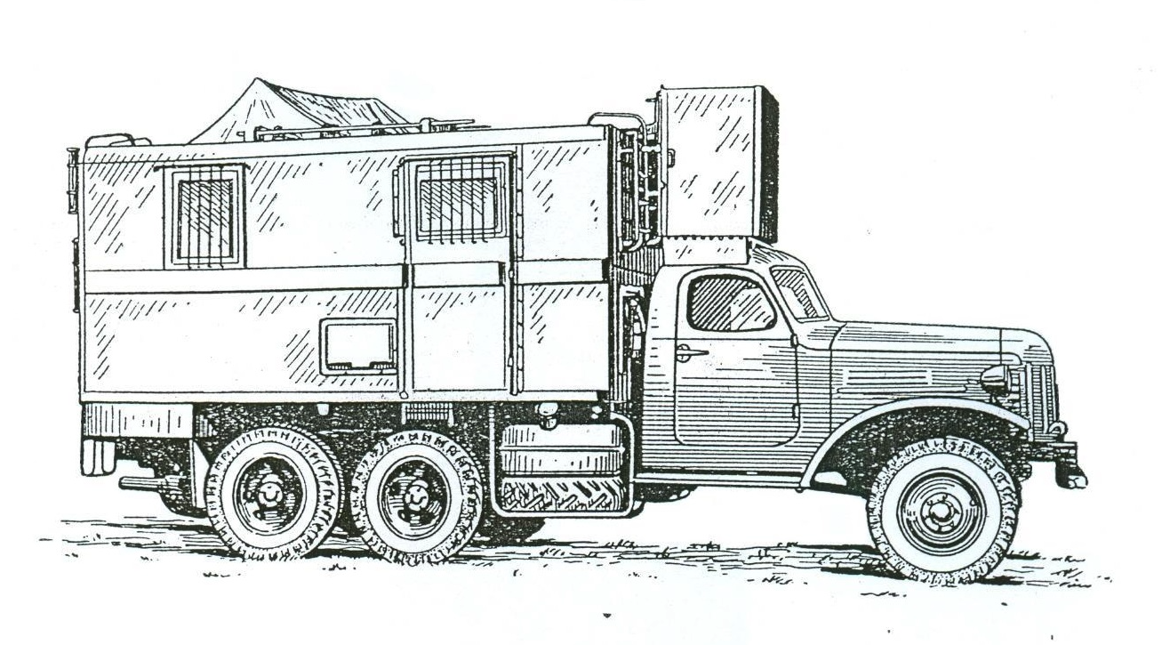
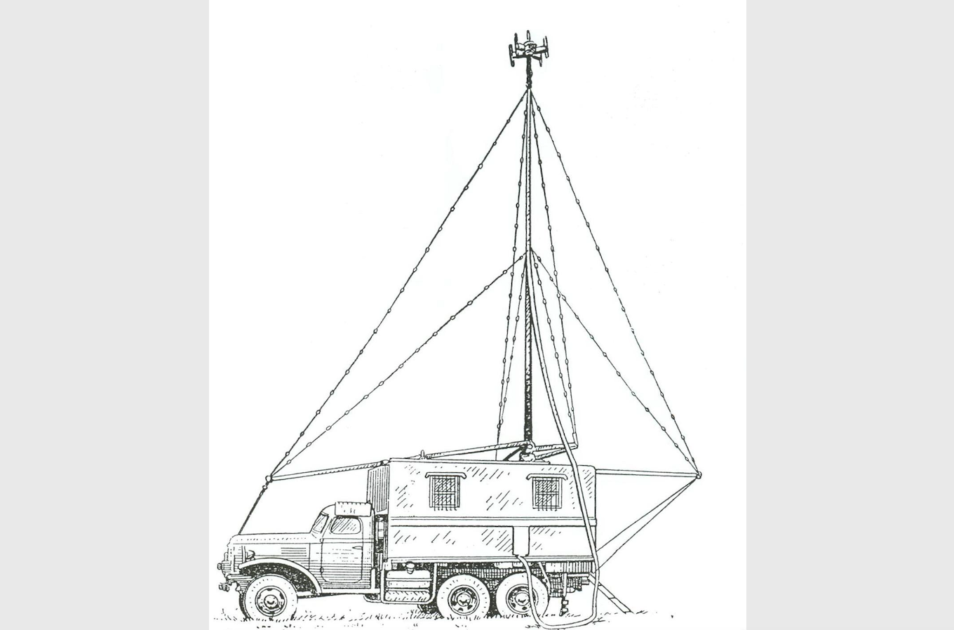
The ARP-4 radio-finder was a transportable version of the ARP-1p stationary single-channel radio-finder, it was mounted on a ZiS-151 truck. It was equipped with a telescopic mast located inside the apparatus room of the radio finder. The mast was raised to the working position (up) by means of an electric motor. When the button was pressed, the "Up" indicator light came on until the lift was completed. The mast was lowered in a similar way, with the difference that the "Down" light was on. The rotation of the antenna head on the mast was also achieved by means of an electric motor. The control of the lifting and rotation of the antenna head was carried out from the radio finder room with buttons on the antenna control board. After lowering the mast, the antenna head was folded onto the roof of the shelter. During transport (driving) of the radio finder, the antenna head was placed in a special container placed on the roof of the driver's cabin and attached to the body wall. The upper part of the mast was then covered with a canvas cover. The antenna head consisted of two "H" type antennas with loop dipoles and one central dipole. Communication with the planes was provided by the R-800 radio. In order to increase the range, an additional VHF car radio RAS-UKW (R-815), RAS-UKW-M (R-824) was used, the panel of which was placed in the radio finder room. The theodolite and the KIP-AP or KIG-AP-1 control and measurement generator with the built-in R-800 radio transmitter were used to align the antenna.
The set of the finder included: reel-to-reel "Dniepr" tape recorder, US-9 radio receiver; KIP-AP or KIG-AP-1 control transmitter; 5 NKN-45 battery bank; generating set ŻES-9 or EP-1 on a single axle trailer. 220V / 380V power supply from a three-phase network or generating sets.
The ARP-5 beacon was a simplified version of the ARP-4 beacon. The main difference was the use of a folding mast raised with a manual winch instead of a telescopic one, which reduced the weight of the mast from 1100 kg to 200 kg. The antenna control board has also been removed. The resignation from the telescopic mast extended and made it difficult to replace the 6F11 lamps in the ARP-5 antenna head. Another difference was the removal of the stationary oscilloscope from the operator's panel and its replacement with the EO-6 portable oscilloscope and the KIP-AP-1 control generator control panel, in their place a container for spare parts was placed.
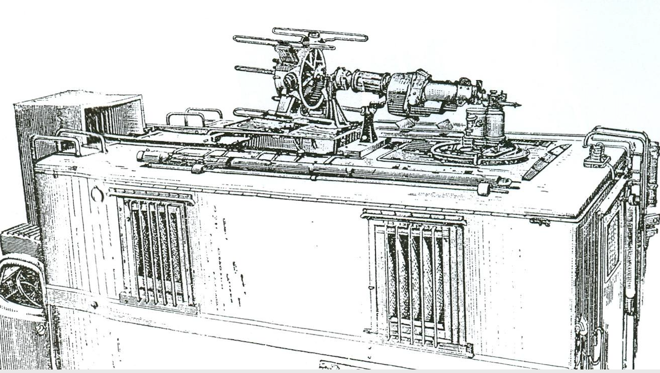
ARP-4 Antenna head. Source: Awtomaticzeskie ukw ARP-4, ARP-5, ARP-1 radiopelengators. Description and instructions after the exploitation
Bibliography:
Automatic ARP-11 radio finder, technical description and operation, Warsaw 1986. Avtomaticzeskie ukw ARP-4, ARP-5, ARP-1 radios. Description and instructions after the exploration, Moscow 1957.
Terrestrial and on-board radio navigation and aviation communications equipment, Poznań, 1972.
Flight insurance in the aviation of the armed forces of the Polish People's Republic, Poznań 1981.
Description and operation of the ARP-6 radio finder, Warsaw 1961.
ARP-6D radio finder, technical description and operation, Poznań 1977.
Knowledge of the devices of the aiming point, Flight Insurance Specialist Training Center, 1979.
Written by Marek Kaiper