Kraków 2013-10-04
The ILS landing system.
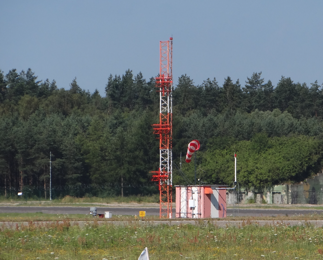
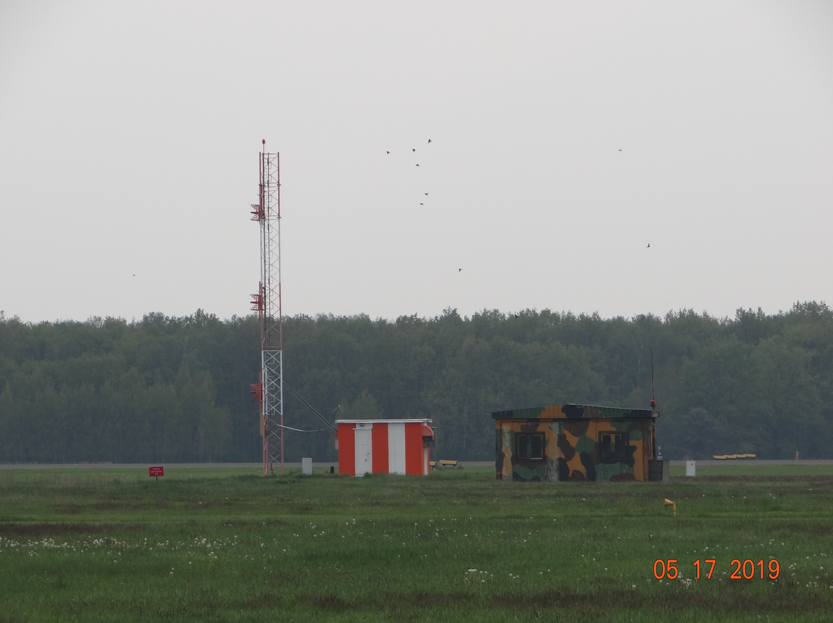
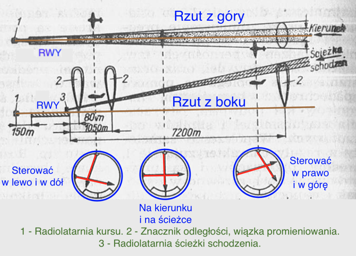
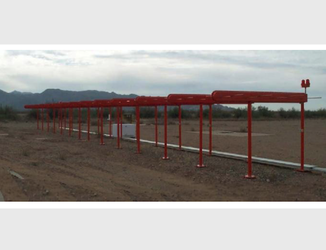
ILS (instrument landing system) is a radio system supporting the landing of an airplane in conditions of limited visibility. It belongs to the navigation systems. The system enables precise guidance of the aircraft from the limit of the range to a certain point on the glide path or even to the touchdown itself. It depends on the category of the system. The system consists of the following devices. A locomotive emitting a signal in the horizontal plane and delineating the axis of the landing path in space. Approach path beacon which emits a signal in the vertical plane and delimits the approach angle in space. Three marker beacons: outher marker (OM), middle marker (MM), and inner marker (IM) for determining the distance and height of the aircraft relative to the runway threshold. Instead of the marker beacons, there may be distance measuring equipment. Beacons emit radio signals of the appropriate frequency (e.g. for the glide path; 150 Hz below the glide path and 90 Hz above the glide path). The on-board equipment of the aircraft receives signals sent by beacons and on this basis the crew controls the aircraft automatically, semi-automatically or manually.
ILS Categories:
There are three categories of ILS (CAT III has three divisions):
Category I (CAT I) - precision approach and landing with a decision height not lower than 60 m (200 ft) above the touchdown elevation, visibility not less than 800 meters (2,625 ft) and RVR not lower than 550 m (1,804 ft) ).
Category II (CAT II) - precision approach and landing with a decision height of not less than 30 m (100 ft) and a RVR of at least 350 m.
Category III A - the decision height is at least 30 m (100 ft) above the elevation of the touchdown zone with an RVR not lower than 200 m.
Category III B - with a decision height of 15 m (50 ft) above the touchdown elevation and RVR of at least 50 m.
Category III C - no decision height and visibility restrictions along the runway, landing can take place in zero visibility.
RVR (runway visual range). Specifies the visibility (distance) at which the pilot of an aircraft can see from the center line of the runway of the runway pavement marking the runway or identify its center line. RVR is expressed in feet (ft) or meters.
The ILS system is now the standard landing aid radio navigation system and every major airport has at least one approach direction served by the ILS system.
Like everything, ILS has some drawbacks. It only has one permanent glide path. It has only 40 channels of work. It is susceptible to interference from broadcasters operating on adjacent frequencies. The area where the antennas are mounted must be level (free from surface reflections). High cost of purchase and commissioning (approximately PLN 4 million in 2008). Therefore, research is continuing on other radio landing systems such as MLS (microwave landing system) or CDGPS (using satellite navigation).
After the Republic of Poland joined NATO (1999), the ILS system became the standard at military airports. Due to the high costs, this system was introduced gradually. For example, it was launched at Krzesiny Airport in 2006, and at Mirosławiec Airport in 2009.
Written by Karol Placha Hetman