Kraków 2017-03-10
Aero-engines - turbojets in Poland - Part 26.
Turbojets in Poland.
In the PZL WSK Rzeszów in the 1950s turbojet engines under Lis-1, Lis-2 and Lis-5 licenses were built. These engines were used to propel Lim-1, Lim-2, Lim-5 and Lim-6 bis aircraft. In Poland, it was hoped that the MiG-21 fighter aircraft, as Lim-7, would be produced in PZL Mielec, and the Tumański R-11 engine in PZL WSK Rzeszów. This did not happen, however, due to CCCP's distrust of Poland.
Poland, however, needed a modern turbojet engine for the newly developed training aircraft TS-11 Iskra. 7.50 kN engines would be sufficient for this type of aircraft, but the aircraft was also to be used for close support sentences, so it was decided to strengthen its thrust to 9.81 kN (1,000 kG).
Because work on the engine is always more time-consuming than developing an airframe, the Rolls Royce Viper 8 engine with 7.80 kN (795.38 kG) was purchased for the prototype of the TS-11 Iskra aircraft. It was an illegal purchase made in Yugoslavia. The TS-11 Iskra aircraft with this engine was flown on February 5, 1960.
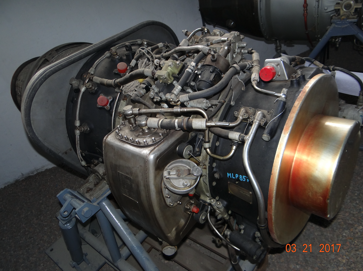
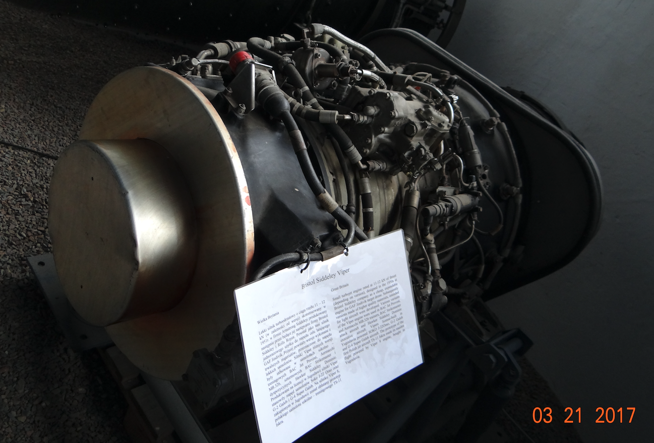
Armstrong Siddeley – Rolls Royce Viper.
Armstrong Siddeley Viper is a British turbojet engine developed and manufactured by Armstrong Siddeley, followed by Bristol Siddeley and finally Rolls Royce Limited. The first start of the engine took place in 1951, and entry into service was 1953. In Royal Air Force, the Viper engine was used until 2011.
The first versions of the Viper engine marked ASV.3 - ASV.7 had a thrust from 1 640 lbf (7.30 kN) to 2 470 lbf (10.99 kN). In 1956, the engine under the name Viper (Viper 8 - 22) was offered to aircraft built outside the UK. The most famous aircraft that the Viper engine received is the Aermacchi MB.326 and Aermacchi MB.339. Viper engines also powered all aircraft constructions developed and manufactured in the now defunct Yugoslavia. The Viper engine was also manufactured under license at Dassault Aviation. The Viper engine has been used in over 20 aircraft constructions around the world.
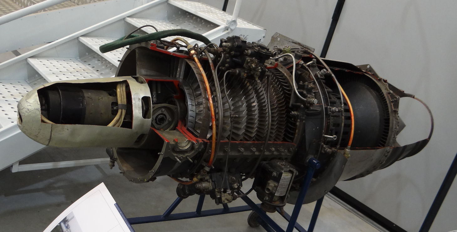
Engine data Viper 9 (ASV.12): length 64.00 in (1.625 m), diameter 24.55 in (0.624 m), weight 249 kg. The engine consists of a 7-stage axial compressor, an annular combustion chamber with 24 injectors, a single-stage turbine. 2,700 lbf (12.01 kN) thrust, 4.3: 1 compressor compression. Air flow through the engine 20 kg / s. Fuel consumption 1.09 lb / hr / lb. Engine thrust to engine weight is 4.9: 1.
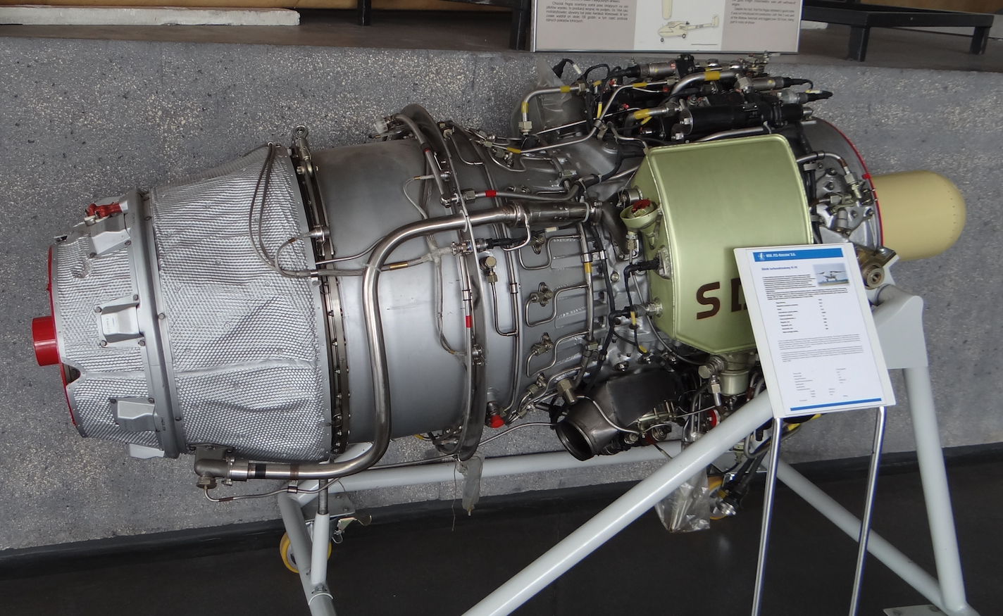
Engine PZL WSK Rzeszów HO-10.
Based on the Rolls Royce Viper 8 engine, in 1960 in PZL Mielec a turbojet engine was developed in the new prototype, which received the designation HO-10. It had 7.65 kN (780 kG) thrust. According to other data 7.84 kN (800 kG). A team led by Eng. Tadeusz Mirski, Jerzy Drożdż and Alfred Sokol. A small series production of this engine was started (1963 - 1966) in order not to stop the development of the TS-11 Iskra aircraft, although the SO-1 engine was planned as the final drive. HO-10 engines were installed in the first production series of the TS-11 Iskra bis A aircraft, which was built since 1963. Later on these aircraft engines were replaced with SO-1, with 9.61 kN (980 kG).
Basic HO-10 engine data: Manufacturer WSK PZL Rzeszów - Poland. Length 2.03 m. Empty weight 260 kg. 7.84 kN.
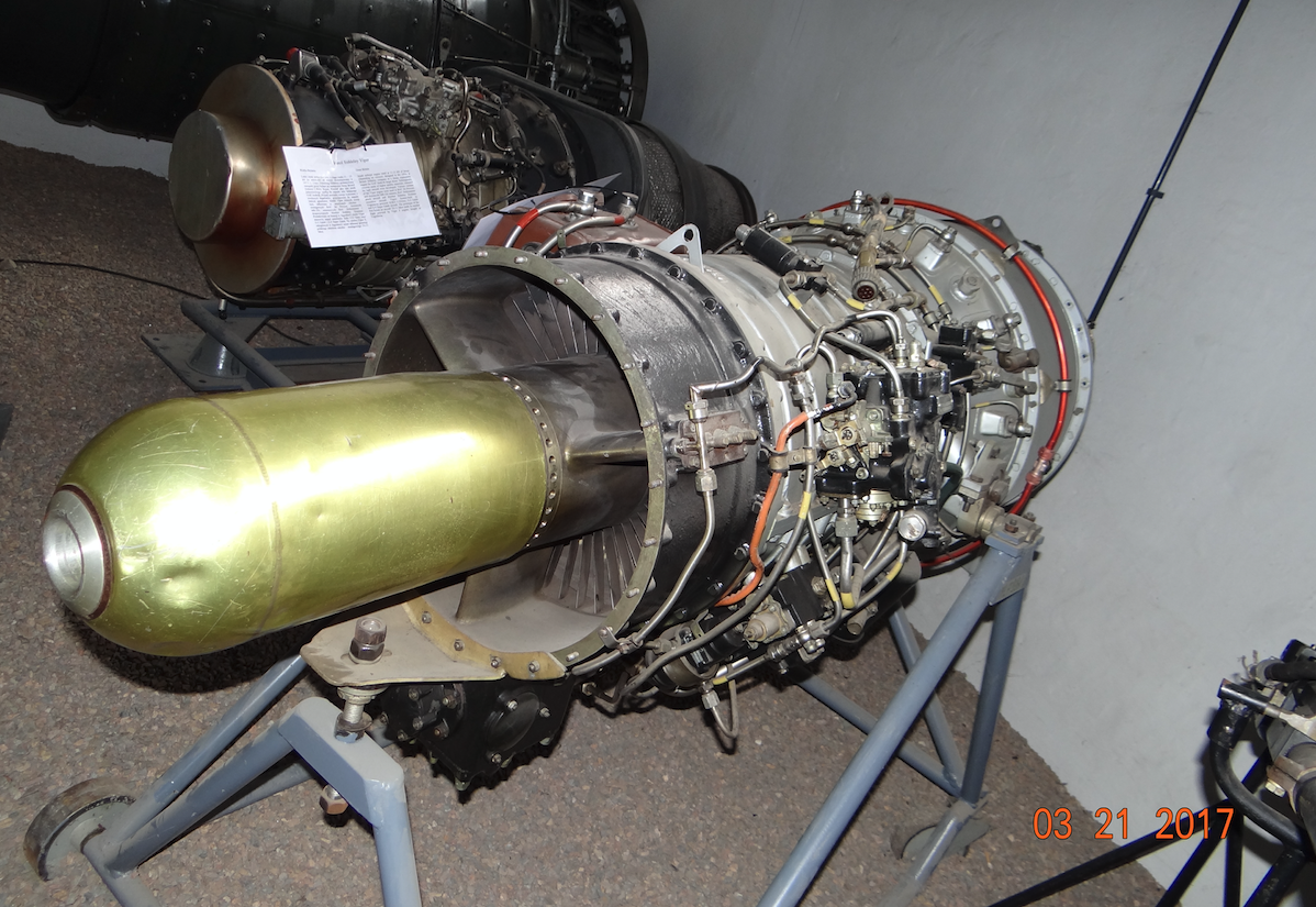
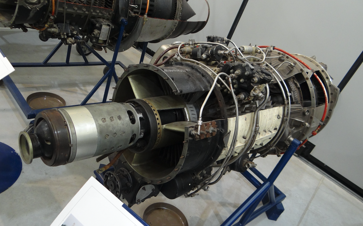
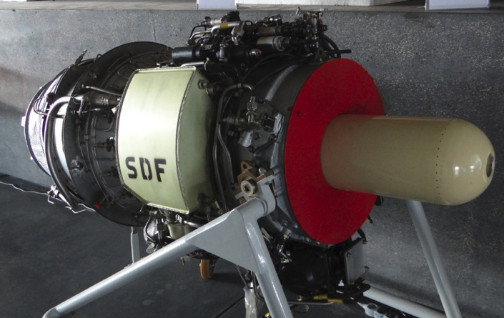
Engine PZL Instytut Lotnictwa SO-1. 1959.
Work on the SO-1 engine (Jet Engine-1) began in 1956 at the Institute of Aviation in Warsaw. The Institute of Aviation had extensive facilities for testing both entire engines and their components. There were two dynamometers, one of which had a silencer installed, which allowed uninterrupted operation, also at night. There were also stations for testing compressors, combustion chambers, turbines, fuel and oil systems. There was no such base in Mielec.
The design of the turbojet engine was carried out by the Engine Plant Institute of Aviation, which before 1960 was enlarged and reorganized into the Center of Engines.
The initial composition of the engineering team was: Kazimierz Rogalski (creator of the engine concept), Jerzy Kucharski (engine center manager), Leszek Piechowski (gear and mechanism specialist), Donat Gruszczyński (fuel system specialist), Jan Chyliński (actually Jan Bierut, son of Bolesław Bierut, communist and soldier of the People's Army, was his father's adjutant, educated in Krakow and Moscow, became an engineer and later deputy minister of Heavy Industry, then ambassador in Bon).
Work on the engine was carried out under the supervision of intelligence and military counter-intelligence, which is why the program received the code name Kashubia. Same as many years later the engine for the PZL-22 Iryda aircraft.
The engine concept was based on the arrangement of one spool supported on two bearings, before the first compressor stage and before the turbine disk. This arrangement was to guarantee easier and shorter engine overhaul. The program assumed the construction of 10 pieces of prototypes, which were built at the Experimental Production Plant in WSK Rzeszów.
The first SO-1 engine was launched in December 1959. To arrive quickly, the first successes and first failures were noted. The engine started easily. He easily reached the assumed string. His gasodynamic system was good. However, there were disadvantages. The lubrication system at the back of the spool was bad. The closed rear bearing system was incorrect. However, the worst was the unwanted vibrations that already appeared at 10,000 rpm. This accounted for only 65% of nominal turnover, or 15,600 rpm. As a result, the engine blurred. The reasons were seen in the inaccurate balancing of the spool (propeller) and not very rigid shaft. Shaft stiffened and accuracy of spool balancing increased. An Italian precision balancing machine was purchased for this purpose. Unfortunately, the vibrations did not stop. The compressor seized up.
Although the engineers had two prototypes, frequent failures caused long downtime in testing. At the beginning of 1962, the third prototype was put to the test. Unfortunately, already at the first start the bearing failed. The fourth prototype of the SO-1 engine was the so-called second version, II-version. It was passed for testing at the end of 1962. This engine already had an open rear bearing lubrication system, with so-called oil loss. This solution significantly improved engine lubrication and the problem was solved. This engine already had the target GSR-ST-6000A current-starter. This prototype significantly accelerated testing.
Unfortunately, the SO-1 II-version engine still had too much vibration and was not suitable for serial production. Stiffening the spool (motive) did not solve the problem. This situation was the reason for a copy of the Rolls Royce Viper 8 engine in the form of the HO-10 engine, which, however, was too weak for the TS-11 Iskra.
At the beginning of 1963, after heated discussions, it was decided to add a third bearing, just after the compressor. It was unequivocally stated that we cannot make a motor with two bearings. This is how the SO-1 III-version engine was created, which proved to be correct and the deadlock was broken. Reach quickly in testing were three engines of this version, No. 6, 7, 8. The number of hours worked on the dynamometer increased rapidly. By March 1964, the engines had worked over 1,000 hours.
Now the fight for structural durability began. The weakest element turned out to be turbine steering blades, the problem of which was solved by changing the material. The front bearing also proved to be weak, whether domestic or imported.
In the autumn of 1963, tests began on a flying dynamometer. The I-28 Nb 119 bomber was used for this purpose. The SO-1 III-version engine was installed in a special movable nacelle. The gondola suspension consisted of two swinging arms that were mounted in the bomb chamber. During the take-off the bomb chamber door was open, and the engine nacelle was closer to the fuselage, but not retracted. After take-off, the gondola with the engine lowered, moving away about 0.50 m from the fuselage, and the bomb chamber door was closed. The safety system consisted of an emergency drop off of the nacelle with the engine. It was never used.
As a result of testing, in April 1964, the SO-1 III-version engine received a certificate with a 100-hour period, except for the front bearing, which only received a 50-hour period. A little later, bearings with silver plated baskets were used. After installing the SO-1 engine on the TS-11 Iskra aircraft, the aircraft set four world records, which issued an excellent certificate to the Polish Aviation Industry.
SO-1 III-version engines began to be built at WSK Rzeszów in 1964. A pre-production series was built there; No. 11, 12, 13. Then the so-called information series was built, which numbered 10 pieces. Prototype engines have reached a service life of over 200 hours with two repairs. In contrast, the information series engines already had a service life of over 600 hours with two repairs. Here is a small explanation. According to Western standards, the engine should run non-stop for 150 hours. It follows that information series engines could pass this exam. Prototype No. 6 had a life of 601 hours, with two renovations. The No. 7 prototype engine had a lifetime of 860 hours, also with two renovations. The SO-1 engine was sent for state tests at the time when one of the prototypes worked 200 hours trouble-free non-stop.
State tests were carried out in December 1966 and January 1967. Unfortunately, engine No. 6SO615 failed in 25 hours of operation due to seizure of the middle bearing due to oil pump failure. The second approach took place on engine No. 6SO616. Here, at 175 hours of operation, the turbine blade was broken. Fortunately, the engine was not disqualified and the engine was approved for conditional use at PZL Mielec, at the Institute of Aviation and at the Air Force Institute of Technology. Based on the collected data, the engine was certified in January 1968 and the TS-11 Iskra aircraft with SO-1 engines went to the Polish Army.
During this operation, it was not without its problems. There was a tear in the compressor blade due to foreign matter being sucked in. There was undulation at idle and stalling in flight due to failure of ASS-1 and APS-1A aggregates. In the Polish Army, the operation of SO-1 engines was almost faultless. Only defects resulting from the intake of foreign bodies into the engine were recorded. During this time (1967) it was decided to build another batch of SO-1 engines in the number of 20 pieces. The engine was constantly improved. SO-1 engines were produced until 1969.
11 years have passed since the start of work on the SO-1 engine, 8 years have passed since the first start. These periods are very similar to those achieved by Western countries. It is true that they were already working on turbo-fan engines. However, considering the socialist planned economy in Poland, there was nothing to be ashamed of. In the eastern kolkhoz, only CCCP, Czechoslovakia and Poland developed turbojet engines. The SO-1 engine program was greatly helped by the presence in the team of Jan Chiliński (Jan Bierut). There was never a statement about the possibility of interrupting and closing the program.
Basic SO-1 engine data: 9.80 kN (999.32 kG) thrust. Manufacturer WSK PZL Rzeszów - Poland. Length 2.15 m. Diameter 0.706 m. Engine weight 303 kg. Air flow through the engine 17,8 kg / s.
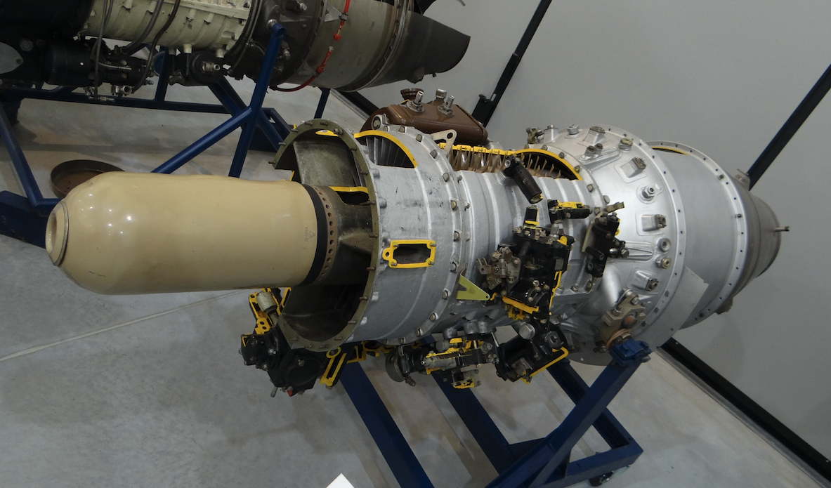
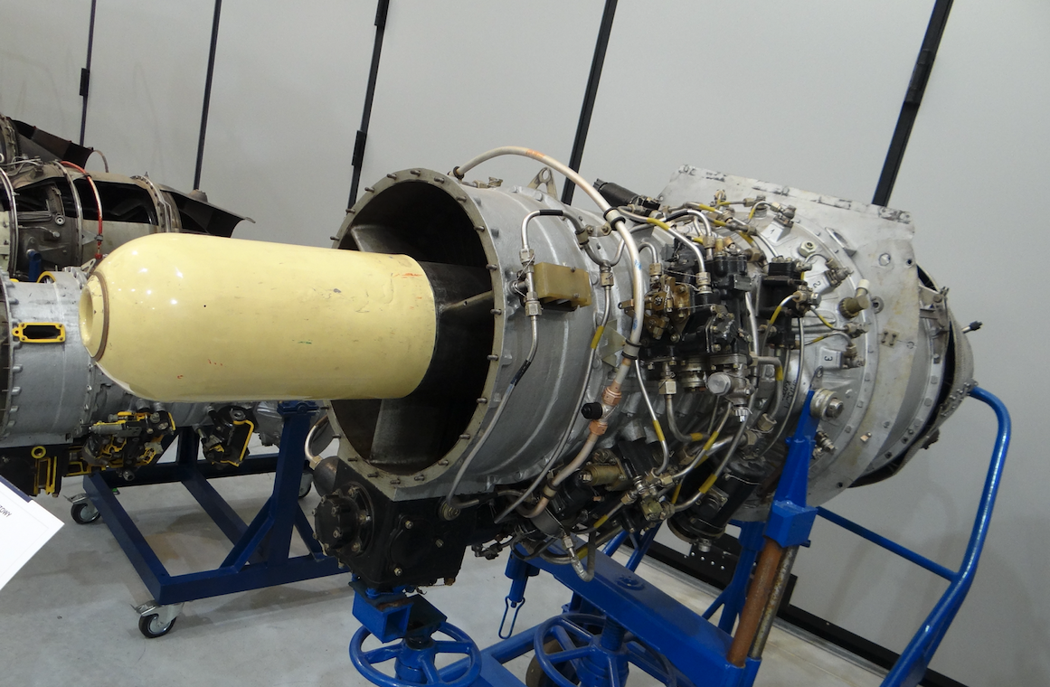
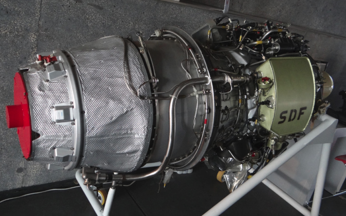
Engine PZL SO-3/SO-3W.
Although the SO-1 engine was approved for operation, work on improving it, and especially on increasing the service life, continued. The program was codenamed Kashub-III, and the designation SO-3. The main tasks were: obtaining a lifetime of 400 hours and durability of basic teams of at least 1,000 hours. Increasing the static compressor work reserve. Fuel system improvement. Installation of de-icing systems. Five new engines were built for the program. The compressors of these engines received changed compressor and stator blades. Turbine discs were made in new technology.
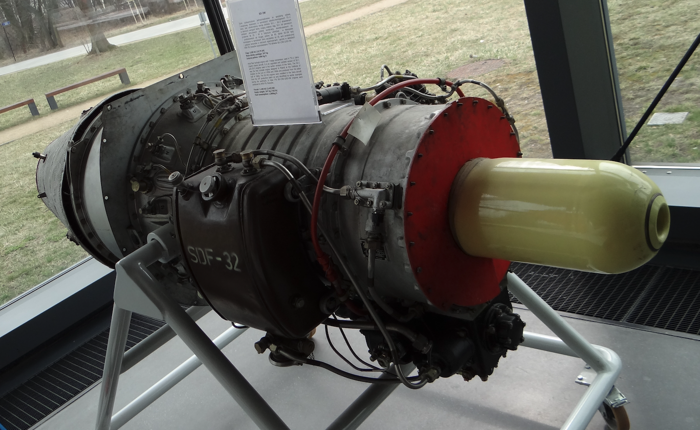
The SO-3 engine has 9.80 kN (999.32 kG) thrust, and the SO-3W engine has 10.80 kN (1 101.29 kG) increased thrust. The service life was extended to 300 hours. The engine stall problem was finally resolved. In 1969, serial production of SO-3 engines was launched. 586 SO-1 and SO-3 (SO-3W) engines were built.
Engine data SO-3 (SO-3W): The engine consists of inlet aerodynamic steering wheels, 7-stage axial compressor, annular combustion chamber, fuel evaporation injectors, single-stage turbine, outlet cone with central cone and cross-section adjustable with inserts. Compressor 4.69: 1 compression. The spool rotates clockwise (of course looking in the direction of flight). Rotational speed up to 15,600 rpm. The air flow through the engine is 17.8 kg / s or 13.8 m3 / s. Engine length 2.15 m, diameter 0.76 m, weight 344 (312) kg. Fuel consumption 29.6 g / (kN · s). Pull to weight ratio 3.4: 1. Fuel type - PSM – 2 according to PN – 72 / C – 96026, P – 2 according to PN – 72 / C – 92026, TS – 1 according to GOST – 10227–62, RT according to GOST – 16564–71. Plunger fuel pump with regulated capacity, type PNZ – 15C for SO – 3 engine or PNZ – 15D for SO – 3W engine. Automatic motor control with shut-off valve and throttling engine and barometric altitude and speed correction, type ASS – 1C1 for SO – 3 engine or ASS – 1D1 for SO – 3W engine. Fuel control automaton with pneumatic switch and acceleration bellows limiting fuel flow depending on atmospheric pressure and pressure downstream of the compressor, ASP-3C type for SO-3 engine or APS-1D for SO-3W engine. Fuel valve - one through valve each, controlling the electromagnetic fuel supply during start-up, type ZOE-100C and a vent protecting against excessive fuel injection, type ZOE-200C. Starting fuel injectors 6 pieces and 12 working ones with direct injection with fuel evaporation fed from separate systems. Mesh fuel filters. Fuel pressure before the injector pump - from 0.5 to 1.5 kgf / cm2. Speed governor correcting the maximum engine speed depending on the compressor pressure, engine speed K-1C for SO-3 engine or K-1D for SO-3W engine. The front spool bearing oil system is closed. The oil system of the middle and rear spool bearings is open with oil loss. The oil system has three mesh filters. The oil tank has 10 liters of capacity. Ester oil AW-30 is used. Oil consumption is 1 liter / h. The oil pressure is from 1.9 to 2.3 kgf / cm2. The engine is started automatically from a 12SAM on-board battery or an airport device. GSR – ST – 6000A current and starter. The R-25AM voltage regulator is used to automatically regulate the generator voltage when the load is changed or the speed is changed within a certain range. Differential relay type DMR-400D, designed to automatically turn on and off the generator to the aircraft's electrical network. Spark plugs, explosive, type SSW – 1X (two pieces) are used to directly create high energy electric sparks. High energy ignition system, type UR – T2, designed to ignite the fuel mixture in a turbojet engine during start up on the ground and in flight. NP-1 adjuster for SO-3 motor or AN-03 for SO-3W program motor, designed for programming the engine start process.
Engine PZL SO-3W22, K-5.
In order not to delay the work on the new PZL I-22 Iryda training and combat aircraft, SO-3W22 transition engines were developed for the aircraft until the Kaszub K-15 engines were completed. The SO-3W22 engine is a SO-3W engine in which equipment and aggregates were moved so that the engine could be mounted in a system of two turbines in the PZL I-22 Iryda aircraft. The SO-3W22 engine has a thrust of 10.56 kN (1 080 daN, 1 100kG). Later the engines were designated PZL K-5.
Basic data of the PZL K-5 engine: 10.56 kN (1 100 kG, 1 080 daN). Engine weight 357 kg.
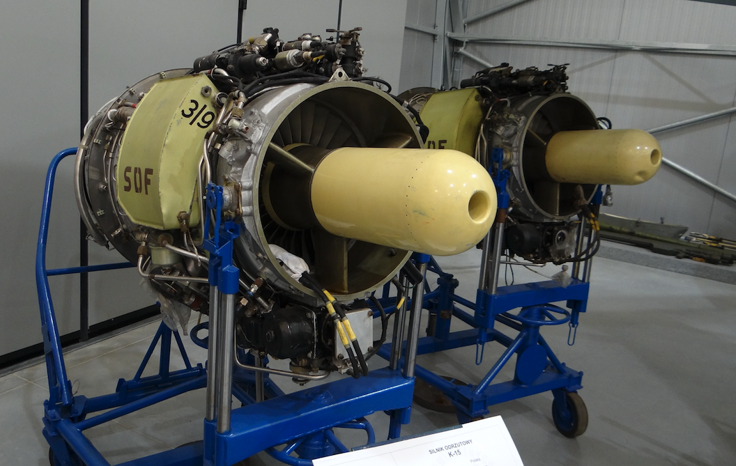
Engine PZL Kaszub K-15.
For the PZL I-22 Iryda aircraft, turbojet engines, single flow, single shaft with afterburning were anticipated from the very beginning. It was decided to rely on the SO-3W engine. The thrust for the aircraft was set at 2 x 1 400 kG, with the possibility of increasing the thrust to 2 x 1 500 kG. Specific fuel consumption was set at a level not exceeding 1 kg / kGh. Reliable operation was required up to a ceiling of a minimum of 15,000 m and a maximum speed of Ma-0.95. In the future, the engine design concept was to ensure a reduction in fuel consumption and an increase in maximum thrust to 1,800 kg. The new engine was to be built in accordance with Soviet or US military regulations, and if they could not be obtained, the use of civil British BCAR regulations was allowed.
The K-15 Kaszub engine was developed at the Institute of Aviation in Warsaw, and was produced at PZL WSK Rzeszów. Julian Fałęcki was the head of the design team. The engine went to drive PZL I-22 Iryda M-93 aircraft. The engine was approved as the basic propulsion of the aircraft in 1994. The engine has a thrust of 14.8 kN (1 500 kG, 3 307 lbf).
The engines are mounted on the I-22 M-93 K aircraft: two single-flow PZL K-15 (Kaszub-15) engines with 2 x 1,500 kG (2 x 1 472-1 480 daN) take-off at 15 800 rpm. Engine dry weight 340 kg. The service life of the main engine units 600-1200 h. K-15 is the next generation of the K-5 engine. The K-15 is a single-shaft, single-flow engine equipped with a six-stage axial compressor with a supersonic first stage, has an annular combustion chamber and a single-stage turbine. The compressor drum impeller has a weld structure made of maraging steel. Blades made of titanium and stainless steel. Electronically controlled aggregates. Installation of the K-15 engine and its installation on an airframe in a similar way as the PZL / K-5 engine.
When we talk about the PZL I-22 Iryda aircraft, it is worth mentioning another engine mounted in this airframe: I-22 M-93 V aircraft. In 1994 one prototype aircraft (1 ANP 01-06 Regions SP-PWE) was equipped with British engines . He was changed to No. 1 ANBP 01-01 leaving the SP-PWE registration. PZL I-22 M-93 V: two Rolls Royce Viper 535 engines with 2 x 1,500 kG (2 x 1 492 daN) starting weight and 358 kg each. Installation of the Viper engine and its installation on an airframe in a similar way as the PZL / K-5 engine.
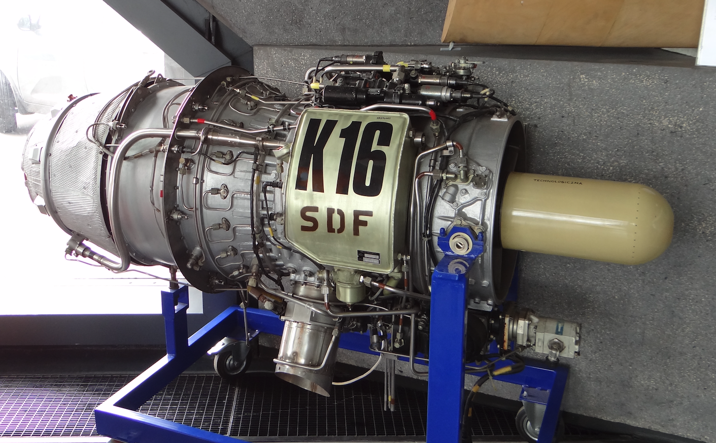
Engine PZL Kaszub K-16.
The Kaszub K-16 engine is a further development of the Kaszub K-15 engine. The engine was created at the Institute of Aviation under the direction of engineer Julian Fałęcki. Compared to the Kaszub K-15 engine, the Kaszub K-16 engine has increased thrust and increased resurs.
The engine transmission (spool) is supported on two bearings. Has a 6-stage axial compressor. The first stage has supersonic characteristics. The first three stages of the compressor are made of titanium.
The Kaszub K-16 engine was created in 1996. In the period from 1997 to 1999 he underwent comprehensive tests. Flight tests began on March 11, 1998. The K-16 engine was mounted on the PZL I-22 Iryda M-93 aircraft. The second engine in the power unit was the K-15 engine.
Basic data of the Kaszub K-16 engine: 15.40 kN (1 570 kG). The engine consists of a 6-stage axial compressor, annular combustion chamber, single-turbine. Engine length 1.56 m, diameter 0.70 m, height 0.89 m, width 0.72 m, weight 360 kg. Compressor compression 5.3: 1. Air flow through the engine 23.5 kg / s. Fuel consumption 1.07 g / kN · h. The rotational speed of the spool is 15 900 rpm. The acceleration time from idle to maximum thrust is 7.5 s.
Written by Karol Placha Hetman